Many LED matrices come with a MAX7219 driver chip or equivalent. Those are great since you program the columns and rows, and they do the line by line scan and refresh for you. Unfortunately, you can't do color mixes with different intensities for each color. For instance the Adafruit LED backpack is super easy to use, but you cannot control each color to mix different shades between them.
Then, I also happened to have some raw LED matrices a dual color one and a triple color one ordered from china, equivalent to these two: https://www.sparkfun.com/products/682 and https://www.sparkfun.com/products/683 . Those didn't come with any driver chip, so that gave me an excuse to program my own code to do line scanning and refresh like many examples you find on the net.
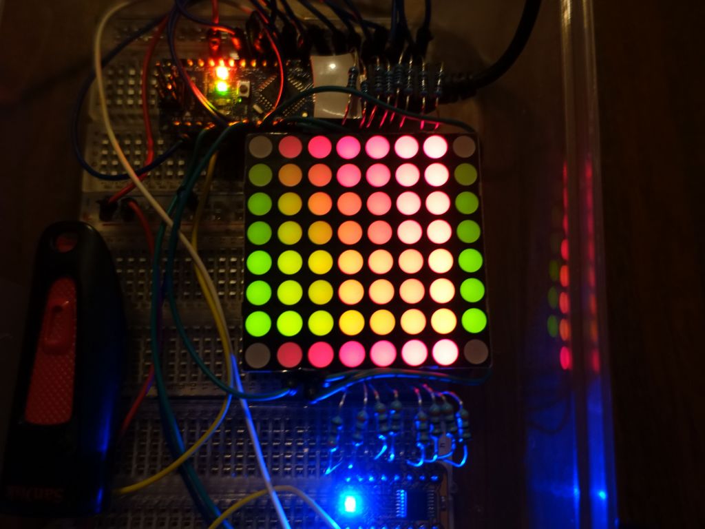
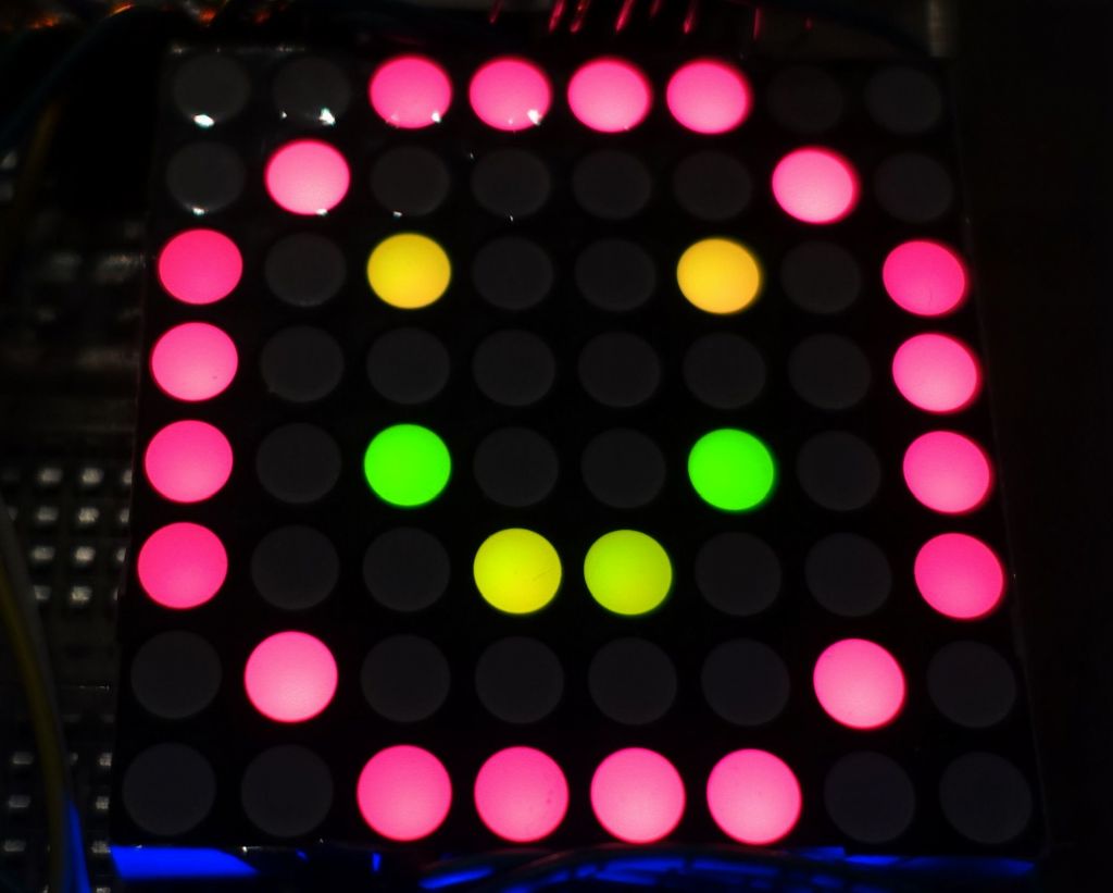
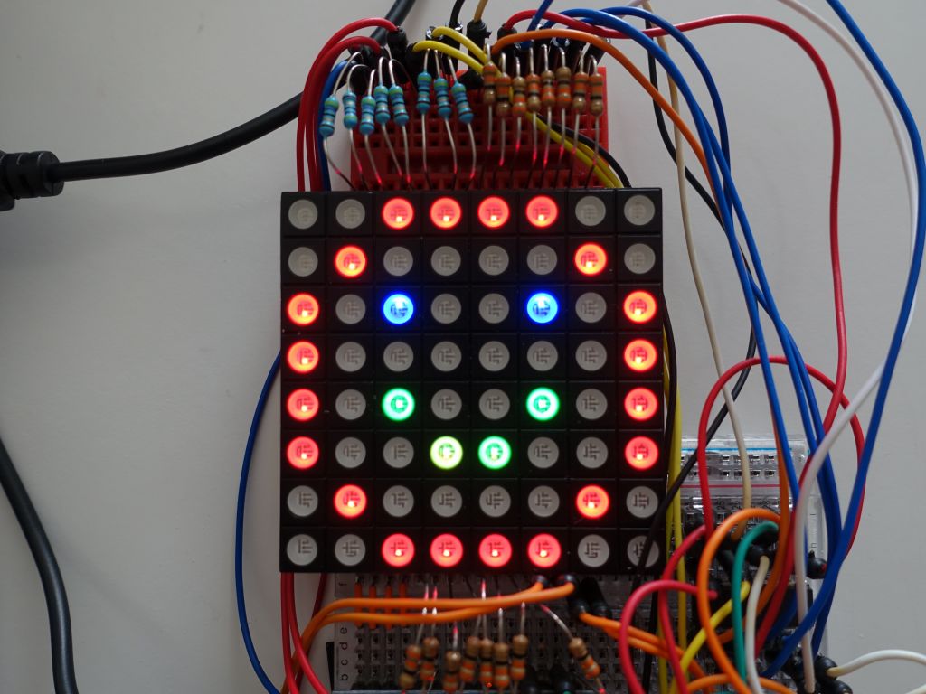
My bycolor matrix has common cathode, green and red on the 2 anodes. Like other matrices you have to disable all the lines, set the rows you'd like for each color, and then turn on the common ground to illuminate those pixels for a little while. Then, you go to the next line, and continue. Many examples do this in the main arduino loop, but I wanted to use Adafruit's excellent Adafruit-GFX library. As a result, I wrote an ISR (interrupt routine) to rrefresh the lines, like an old cathodic raw tube, in the background, while leaving the main loop for programming what you want to do and display. This soon allowed me to display the smiley face bitmap from the Adafruit LED Backpack library.

from here

to here
This was pretty major accomplishment for me since I wrote a generic C++ library that could allocate an array of any size (it supports anything, not just 8x8), and do all the work in the background in an ISR. I then got busy with other projects and hobbies.
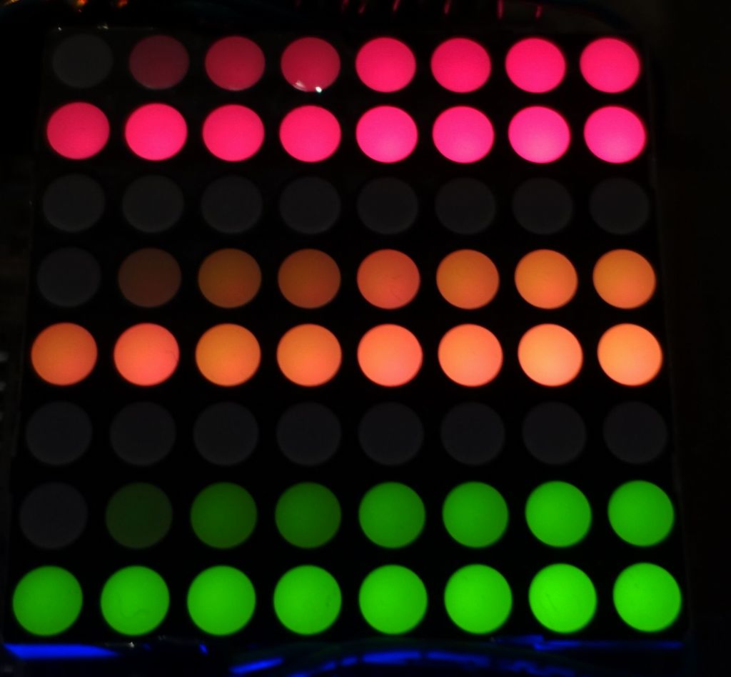
Later, I came back to this and added code to support more than one color, and especially support programming an LED array of 1 to 3 separate colors wired either directly or via shift registers, or a combination of the 2 (shift registers save pins, but also make IO 50% slower). By then I was hitting issues where I had to refresh the lines very quickly (200 microseconds) to allow for 16 shades per color and still offer a 40-50Hz refresh rate for the whole array. If my refresh became slower than 200 microseconds, I could not support 16 shades (4 bits per color) without getting too slow and creating an array that would visibly flicker. I fixed this by doing the following:
I've published my resulting code here: Multi Color PWM LED Matrix Driver. While it uses more resources than the adafruit backpacks, it's cheaper in hardware and ends up giving more flexibility (many more colors).
Before you ask me for help, READ THIS PLEASE :)
But basically you should get the basics working before trying my library, make sure you can turn on LEDs one by one, understand the basics, and then you can use my library which will give you much faster access to your matrix while offering a GFX graphical library on top.
You can look at the results here:
The original Adafruit::GFX library didn't support multi color bitmaps, but I added support for it here: https://github.com/adafruit/Adafruit-GFX-Library/pull/39
After doing the above, I went to add support for Tricolor Matrices, which was not much work, except for adding those its:
This was all added to my LED-Matrix library here: https://github.com/marcmerlin/LED-Matrix
>
If you'd like to buy the tricolor matrix I used, here are some links:
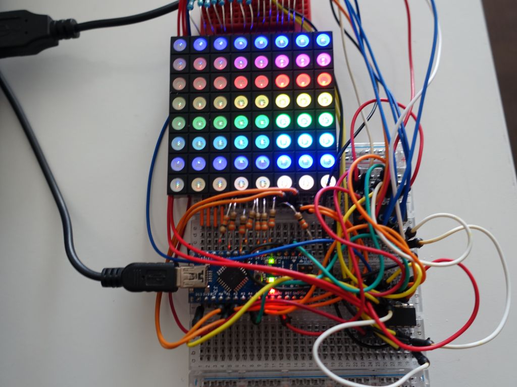
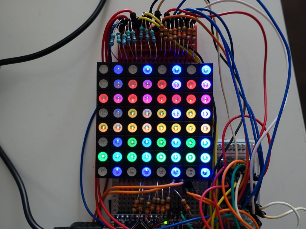
Again, the pictures don't do a good job showing the PWM values because of the CCD trying to capture a consistent amount of light. Also, anything close to white uses all 3 LEDs, this draws too much current from my arduino on the common anode. Before I add FETs or ways to improve current per line, it's still good enogh for demos. This setup uses 2 shift registers for 16 pins (blue and red), while green is connected directly to 8 pins, and 8 pins for common anode (which is where the current for 3 LEDs at once is lacking):

generating circles with the Adafruit::GFX library
Here's a video demo:
Links to other pages about this topic: