| |
π
2013-11-10 00:00
in Computers, Linux, Linuxha
Links to cameras:
DCS900
FI8904W
NCB541W
FI8910W
FI8920W
FI8921W
Aircam
Edimax3115w
F3210
FI9826PB
FI9805P
FI9900P
NCM625GA (aka Wansview Q1)
NCM751GA (aka Wansview W1)
Wansview K1
Wansview W2
Wansview Q2
Reolink RLC-410
Wansview K2
I hearby want to thank Wansview for giving me some of the above cameras for review (I bought some of them on my own, and after seeing my reviews, they asked me to test and review a few more). Note that while wansview cameras do not offer the sharpest 1080p pictures I've seen (Zavio and FI9900 win, even I hate foscam), the nice things I've written on wansview are not based on the free cameras, but the fact that they have always answered my support queries, including the technical ones showing issues with the firmware, and fixed the firmware after that (including making it work on linux and other other operating systems), while Foscam tells people that they're running the wrong version of windows, and that's it.
zavio truly sells good cameras, but sadly they cost more than double, which may be a bit out of reach for many people.
Zoneminder
I have tried a bunch of IP cameras with linux and zoneminder. Here is a short review of them below if that helps others.
One good page to know about is ispyconnect, which gives all the entrypoints for many cameras:
http://www.ispyconnect.com/man.aspx?n=foscam
http://www.ispyconnect.com/man.aspx?n=wansview
http://www.ispyconnect.com/man.aspx?n=zavio
Camera in 2009
Dlink DCS900
My first IP Cam was a Dlink DCS900. Today, it's utter crap, the picture is bad, the camera is slow, but back in the day it was cheap-ish and there weren't many other ones:


Cameras in 2013/11
Foscam FI8904W
This is an outdoors camera. It's not wide angle at all, which I don't like, and it's low res (640x480), but the picture is decent enough for that resolution:
Wansview NCB541W
It's a clone of the FI8904N. The firmware isn't great, but it works well enough for image capture and it's the cheapest you'll find for 480p with a motorized base _and_ night view.
Foscam FI8910W
Similarly the FI8910W is ok enough for 640x480, but don't expect miracles:
Because it wasn't wide angle enough, I got a 3rd party (cheap) wide angle F2.0 lens for it. It blurs the picture around the edges quite a bit, but gives me the shot I wanted:
Foscam FI8920W
It's supposed to be an HD camera (720p), but the picture is horrible and the web interface too (does not work with linux). It's not even wide angle. DO NOT BUY:
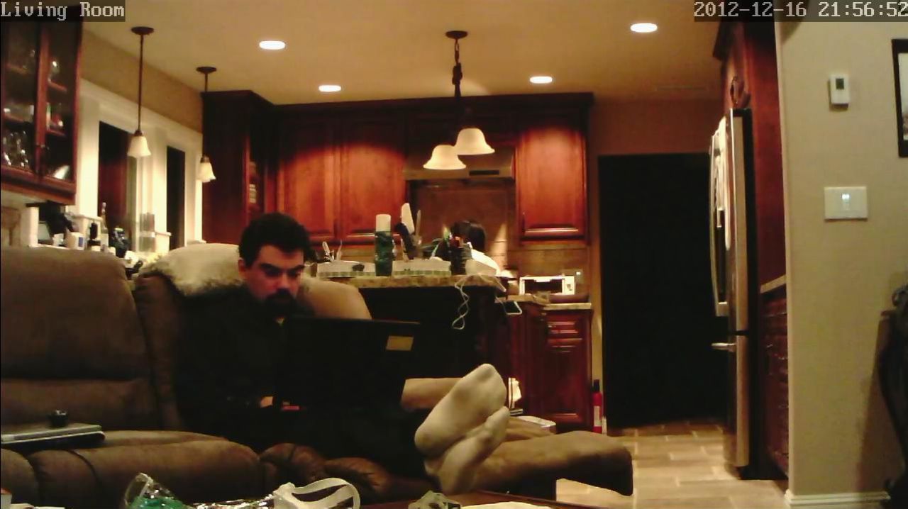
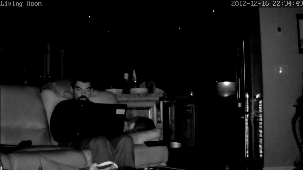
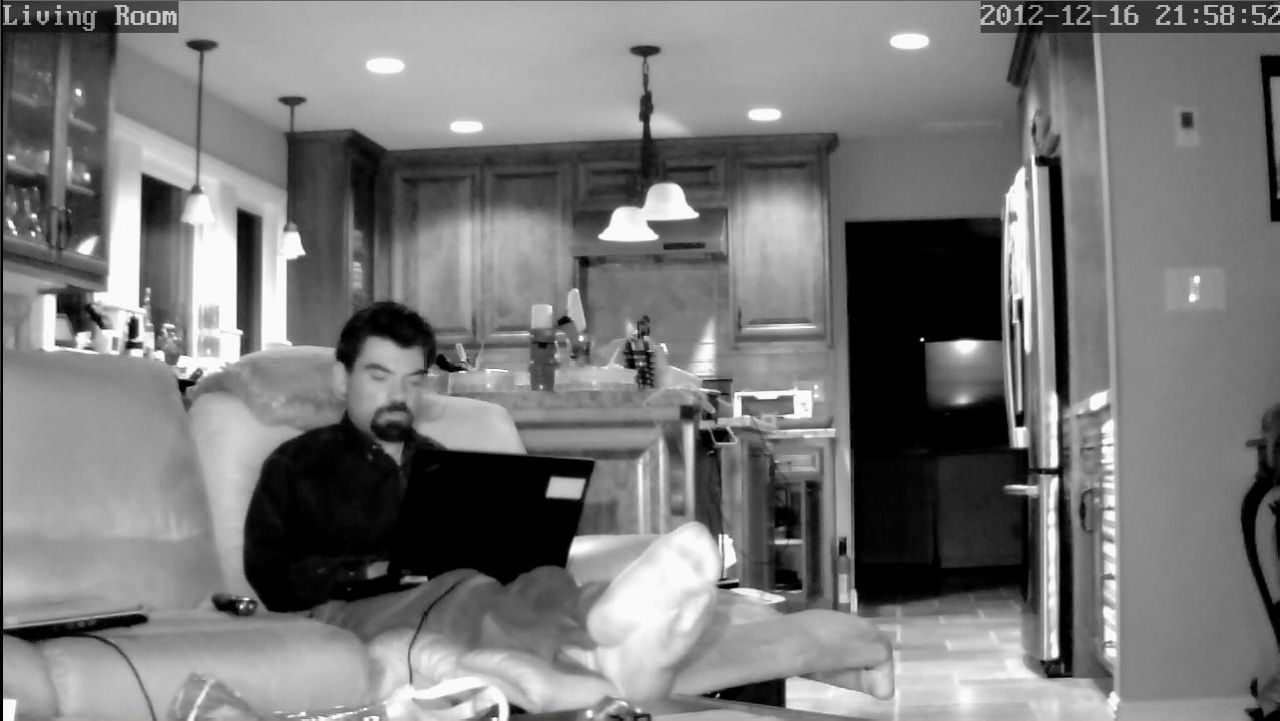
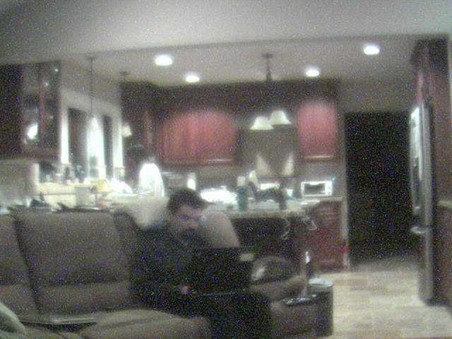
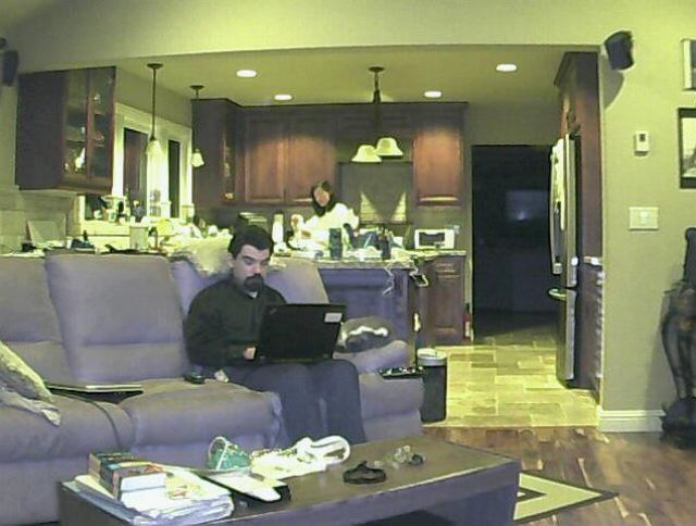
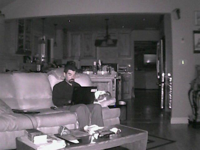
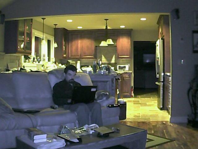
Foscam FI8921W
It's the not as bad version of the FI8921W. To be honest, the 720p HD picture is still blurry, but it's better than 480p. You get what you pay for. The web interface does not work with linux but you can capture screenshots from it with zoneminder on linux after you've set it up. It also has an RTSP stream, but I found it often gave me frames where the picture was aborted half way (actually I found out later that reducing the frame rate seems to fix this), so I use image capture instead of RTSP for zoneminder.
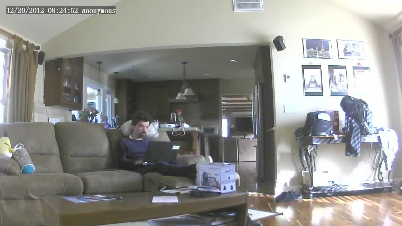
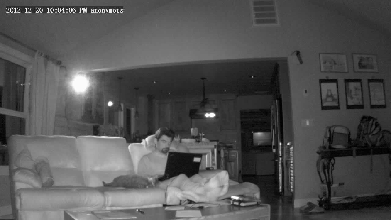
I also changed the F2.8 lens to a wider dealextreme F2.0 lens that's blurry around the edges:
Ubnt Aircam
It wins for the very wide angle and cheap price for 720p, but that's because the sensor is not 720p, only the output is.
If you take a 480p shot and you blow it up to 720p, it looks almost the same. Sad... The newer firmware offers image capture if you turn off authentication, but I didn't get it to work well with zoneminder (it's too slow), so I use RTSP. I would not really recommend this camera unless you want the very wide angle. Note that some cameras ship blurry because the lens (very very hard to turn, it's stuck with glue I think), is not focussed. At times, it'll also show you wrong colors.

out of focus out of the box, this is kind of sad

this is only barely better than the 480p version but great wide angle

480p picture blown up to 720p to compare with 720p 'native'
Edimax 3115w
This is a nice cheap camera with an honest resolution of 960p. The caveats are that it's not motorized, and it does not have night/IR vision, but otherwise the picture and resolution are good and you can't beat them for the price (assuming you can still find it for sale anywhere)
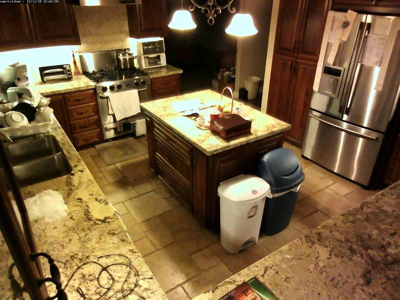
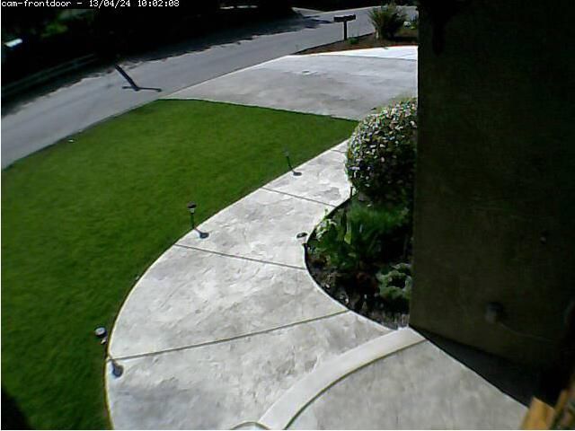
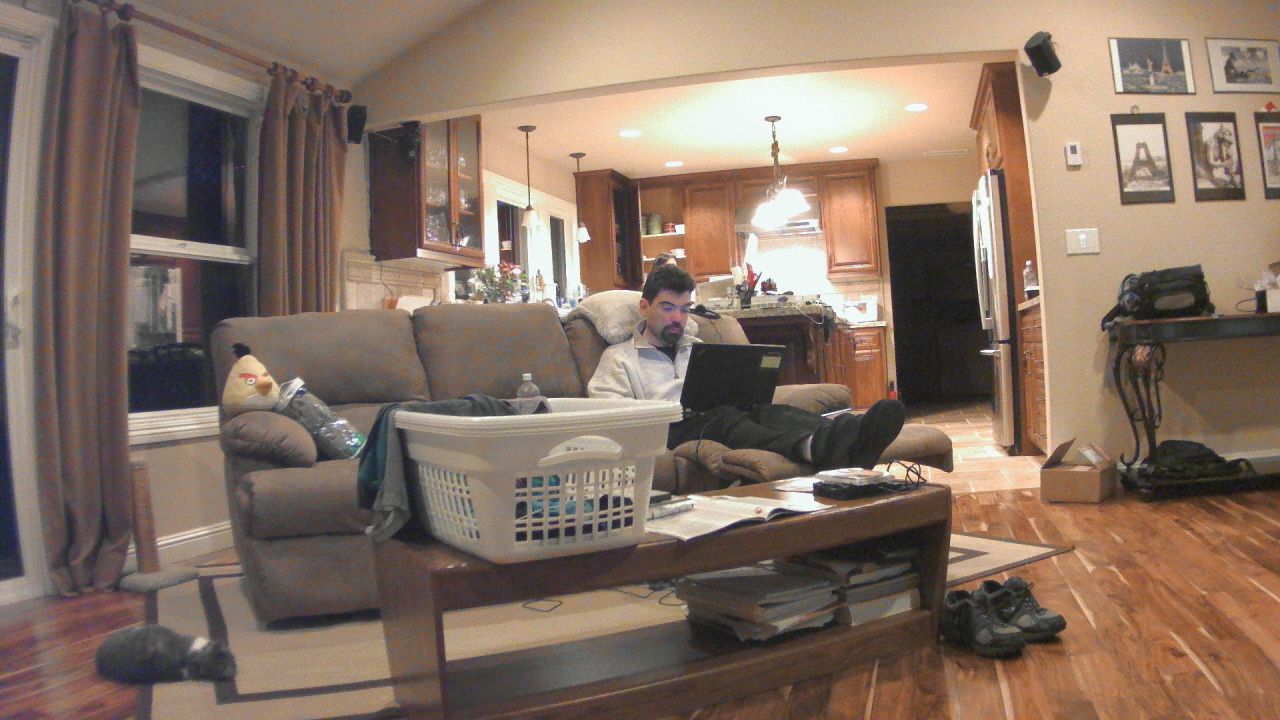
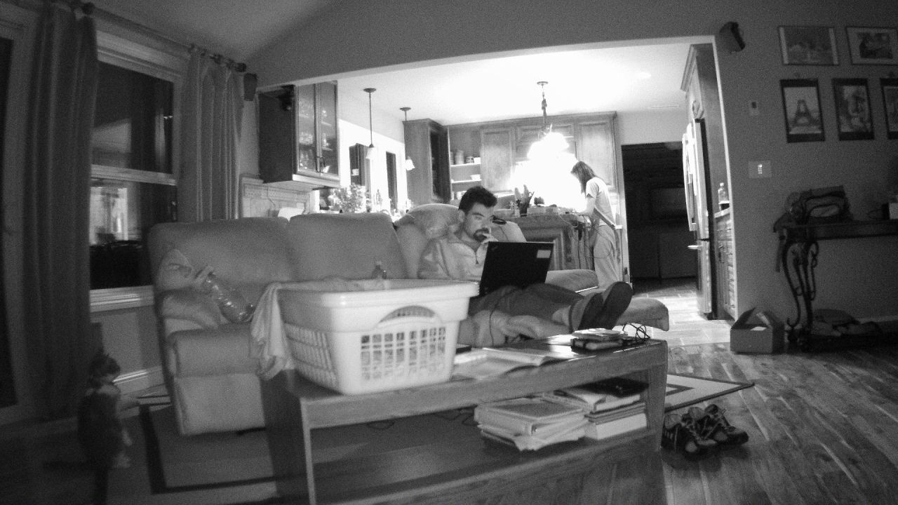
Zavio F3210
It's more expensive ($260), but the picture is fantastic, even in 1080p (reduced here for the web page). Too bad it does not come motorized, and for Wifi you'll need the F3215 which is not motorized either ($280).
The web interface and protocol support are fantastic. This is a camera that all other manufacturers should inspire themselves from. You can fully configure it in any browser (including from linux of course), and see the live view without any special plugin.
Cameras in 2015/08
My old Foscam fi8904w died (it was my only outdoor camera), so I looked at replacements. Sadly foscam only got worse software/firmware-wise, sometimes even making cameras that work with virtually no OS (including new versions of windows in some cases), and they continued to have lots of fake 5 star reviews on amazon, which is enough of a reason not to by from them anymore.
A few cameras I looked at first though:
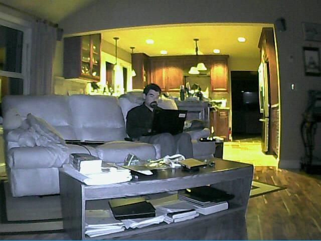
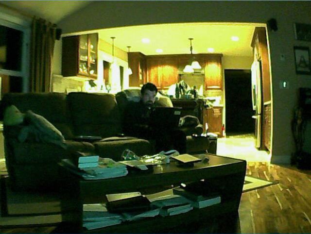
Foscam FI9826PB
Don't buy this, get the cheaper Wansview NCM625GA/Q1 (or Q2) which comes with higher resolution and no cheating fake reviews on amazon.
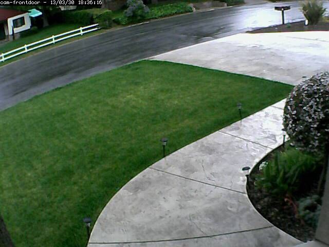
Foscam FI9805P
This one might have worked, again if you forget all the fake amazon reviews, but it's superseeded by the FI9900P.
Foscam FI9900P
The amazon reviews are saying: good camera quality, and questionable firmware with bugs, a foscam specialty still...
I ordered one out of morbid curiosity and to replace my outdoors Foscam FI8904W which just died, but really I (or you) shouldn't be giving any money to Foscam anymore...
If you don't mind spending more ($300), the Zavio B6210 seems like a good serious replacement.
Anyway, here's what I found on the Foscam 9900:
The firmware is even more horrible than it was before. I could not even get it to display a picture in windows with MSIE and their stupid windows only plugin that I shouldn't even have to trust to see a picture. I was able to change video settings on windows, but not see the picture.
With the android software, I can see the picture/video, but not change the video settings
And get this, if I try to login on linux, I cannot even login. Yes, login denied without the stupid windows plugin (i.e. I cannot even access settings and non video related stuff).
If you guessed that I think Foscam sucks by now, you guessed right. First to me, they look like liars and cheaters by what really looks like buying fake reviews on amazon, and then in the last 2 years, they actually made their web interface worse since the FI8921W where you could at least login on linux and change settings.
While I'll repeat that life is too short to deal with this crap and give money to that company, I used jpeg URL ( /cgi-bin/CGIProxy.fcgi?cmd=snapPicture2&usr=user&pwd=pwd1 ) to make it work with zoneminder, and it works well enough. As other reviews have said, the optics are actually quite good, I do like the very wide angle picture without barrel effect:
Too bad that Foscam's firmware sucks so much, the optics are good now. If you need an outdoor camera, and value your time and sanity a few dollars, I'd recommend the Zavio B6210. If an indoor camera used outdoors with light weather proofing is good enough, try the cheaper and somewhat better Wansview NCM625GA/Q1 below (although its picture isn't as wide and show barrel effect):
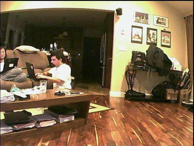
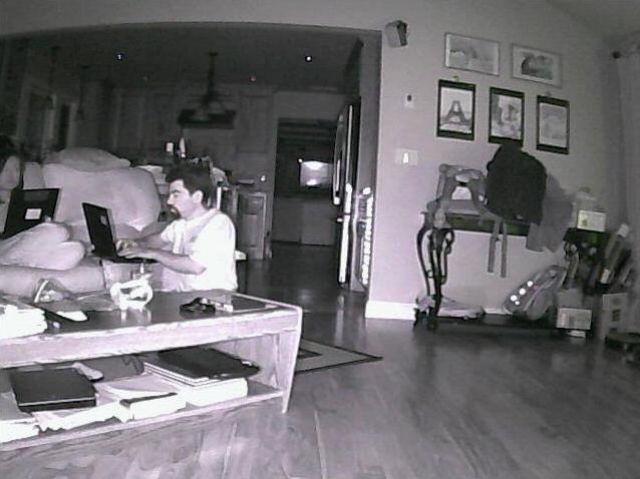
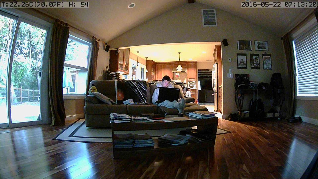
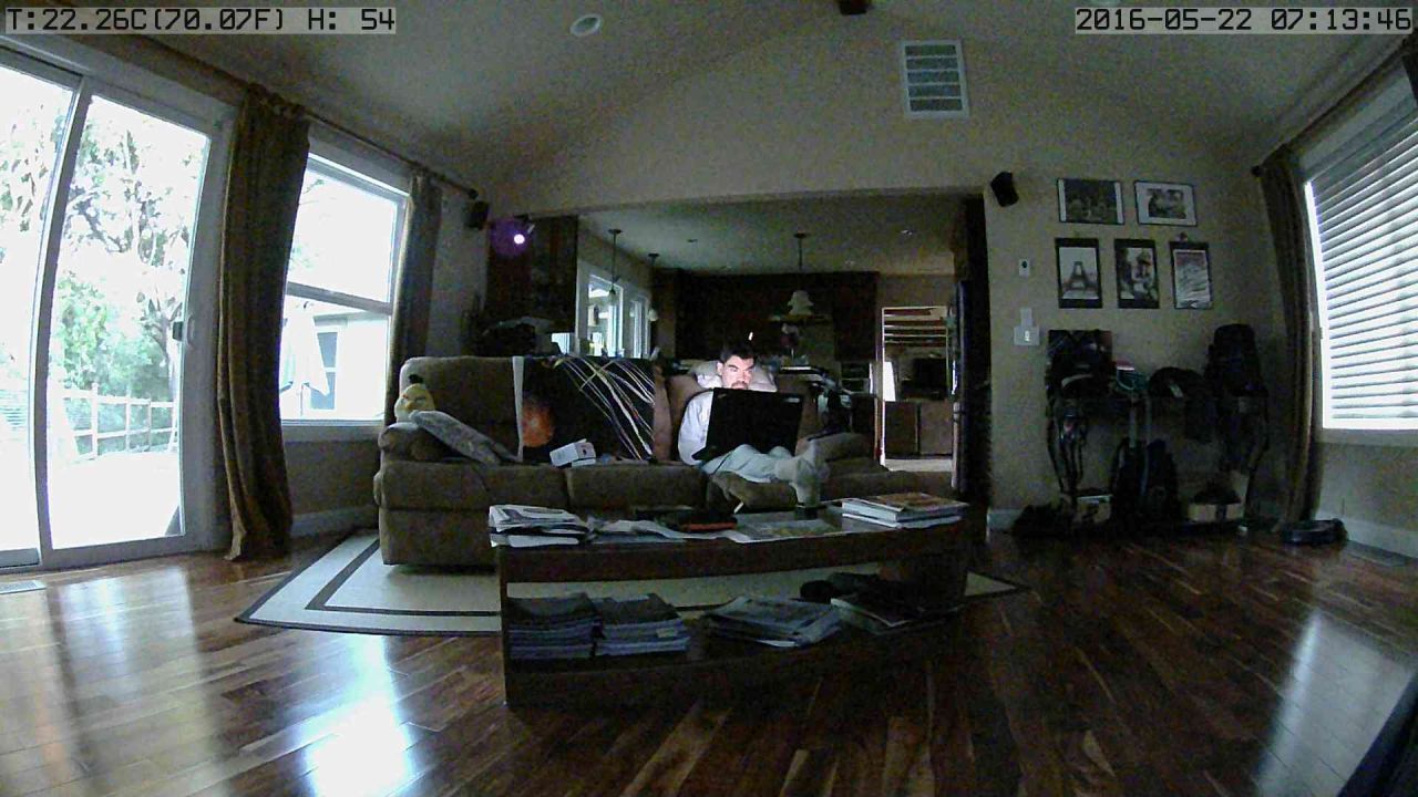
Wansview NCM625GA (aka Wansview Q1)
I ended up continuing with an indoor camera that I'm going to use outdoors. A Zavio F3215 would have been very good, but this new Wansview is half the price and is motorized. It's much much better than the old NCB541W I have (and actually that was a very good camera for the price too). The Wansview NCM625GA is sold on amazon as Wansview 1080P 2.0MP WiFi Wireless IP Security Camera, Full HD.
Note that there is new firmware for this camera. The original firmware was mostly windows only, but the new one has a flash interface that works on linux and most operating systems.
Cons:
It used to require a windows plugin, but now it works with flash too on most operating systems (including linux)
Pros:
Price/features is unbeatable ($80), video quality is good
Nice wide lens (maybe not what you needed, but that's what I wanted)
the motorized mount almost has 360 travel
relay outputs if you care about that
Updates:
If you install firmware 0.40 and this firmware patch I got from Wansview (both can be installed in the web upload interface), http://ipaddr/mjpeg/snap.cgi?chn=0 now returns a proper Content-Type: image/jpeg header and will work with Zoneminder and other software that expects a jpeg. You can also get official firmware updates from this site: http://www.wansview.com/Service/download/25.html
Info:
Turns out you can get simple jpegs from that camera without a plugin. The magic URL is http://ipaddr/mjpeg/snap.cgi?chn=0 . Note that the firmware did not return a proper "Content-Type: image/jpeg" header, so the jpeg URL does not work with zoneminder and may not work with other software. This is now fixed with a firmware patch_.
I installed the recommended iSmartViewPro on android, scanned the QR code on the back of the camera, and had it working instantly.
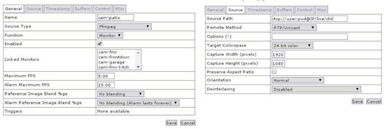
The video works fine on linux with ( vlc rtsp://ipaddr/live/ch0 , vlc rtsp://ipaddr/live/ch2 , vlc rtsp://ipaddr/live/ch3 ).
PTZ can be controlled with GET ipaddr/hy-cgi/ptz.cgi?cmd=ptzctrl&act=left|right|up|down|stop|home|hscan|vscan (you can also add &speed=1-4 for a slower/faster scan speed).
Move to a preset: GET ipaddr/hy-cgi/ptz.cgi?cmd=preset&number=1&act=goto (I gathered those by dumping strings in the npHYPlayer.dll they provide for windows).
From the command line, try wget -q -O - --user=admin --password=pwd 'http://ipaddr/hy-cgi/ptz.cgi?cmd=preset&number=2&act=goto'
To move the camera just a bit to the left, try this: wget -q -O - --user=admin --password=pwd 'http://ipaddr/hy-cgi/ptz.cgi?cmd=ptzctrl&act=left&speed=2'; sleep 1; wget -q -O - --user=admin --password=pwd 'http://ipaddr/hy-cgi/ptz.cgi?cmd=ptzctrl&act=stop&speed=2'
It works fine with zoneminder 1.28 although I have to configure the 1080p stream on the camera to only be 3fps, or my zoneminder backend cannot process it quickly enough and the picture gets truncated (also there is up to a 5 second delay, but that seems to be true for zoneminder with many RTSP streams). If this does not work well for you, you can also simply configure zoneminder to pull the jpeg without using RTSP.
With the newer firmware, you can now do jpeg image capture too like you would with any basic webcam:
http://wansview-ncm625ga-1/mjpeg/snap.cgi?chn=0 gives you a single jpeg snapshot (which on newer firmware like 48 is 1920x1072 instead of 1920x1080, beware!)
http://wansview-ncm625ga-1/mjpeg/stream.cgi?chn=0 gives you an mjpeg stream that works with zoneminder but for me it gives a lower frame rate (1fps while I can do about 5fps on jpeg pulls from snap.cgi).

The 1920x1080 shots are truncated to 1280 for display on this page
Wansview NCM751GA (aka Wansview W1)
Wansview just came out with a competitor to the Foscam 9900, it's priced at the same $150 (now $100-ish 2016/12). If you need a cheap 1080p outdoors camera, and you hate foscam like I do (as explained above: bad firmware, and dishonest fake reviews on amazon), it's a decent option. However, the optics/video capture are inferior to both the foscam 9900 and the Wansview NCM625GA. For some reason, the 1080p picture looks like a blown up burry 720p or maybe 480p picture (this turned out to be due to my lens being out of focus, it's better after I fixed that). Also this camera is big and heavy compared to the Foscam 9900 (try the W2 instead).
Please read the Wansview Q1 review for details on magic URLs to use, and firmware updates.
This camera was superseeded by the Wansview W2 which is both much smaller and cheaper. Honestly, the only advantage of the W1 is the onboard storage if you care about that. For remote capture support, the W2 will be a much better bet (and almost half the price).
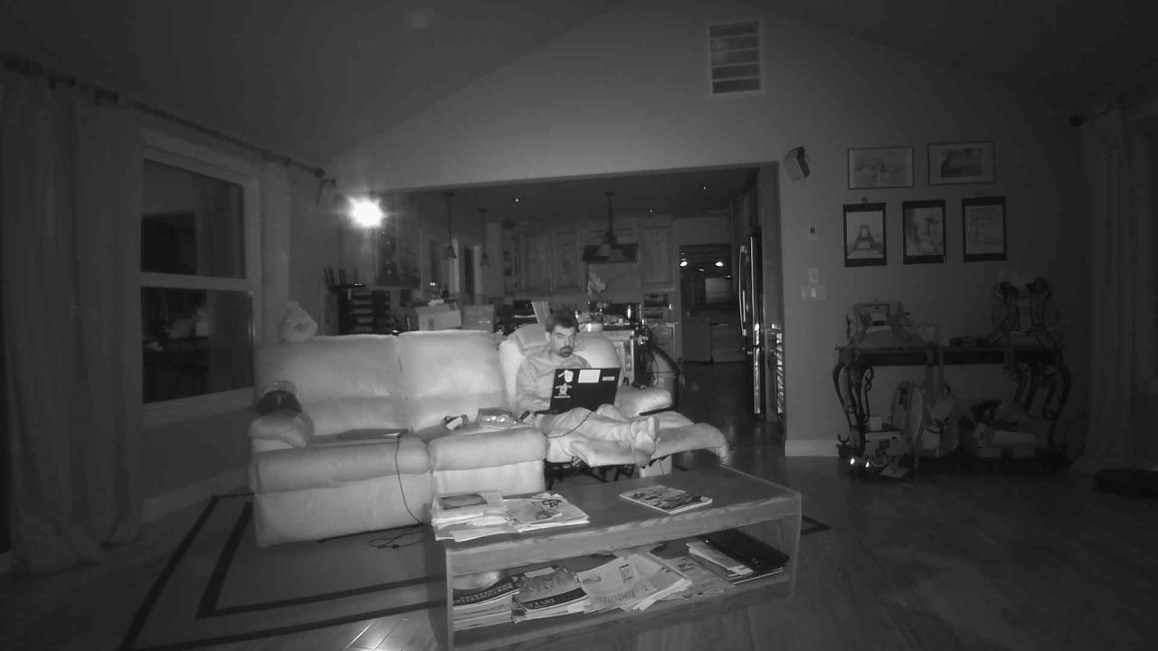
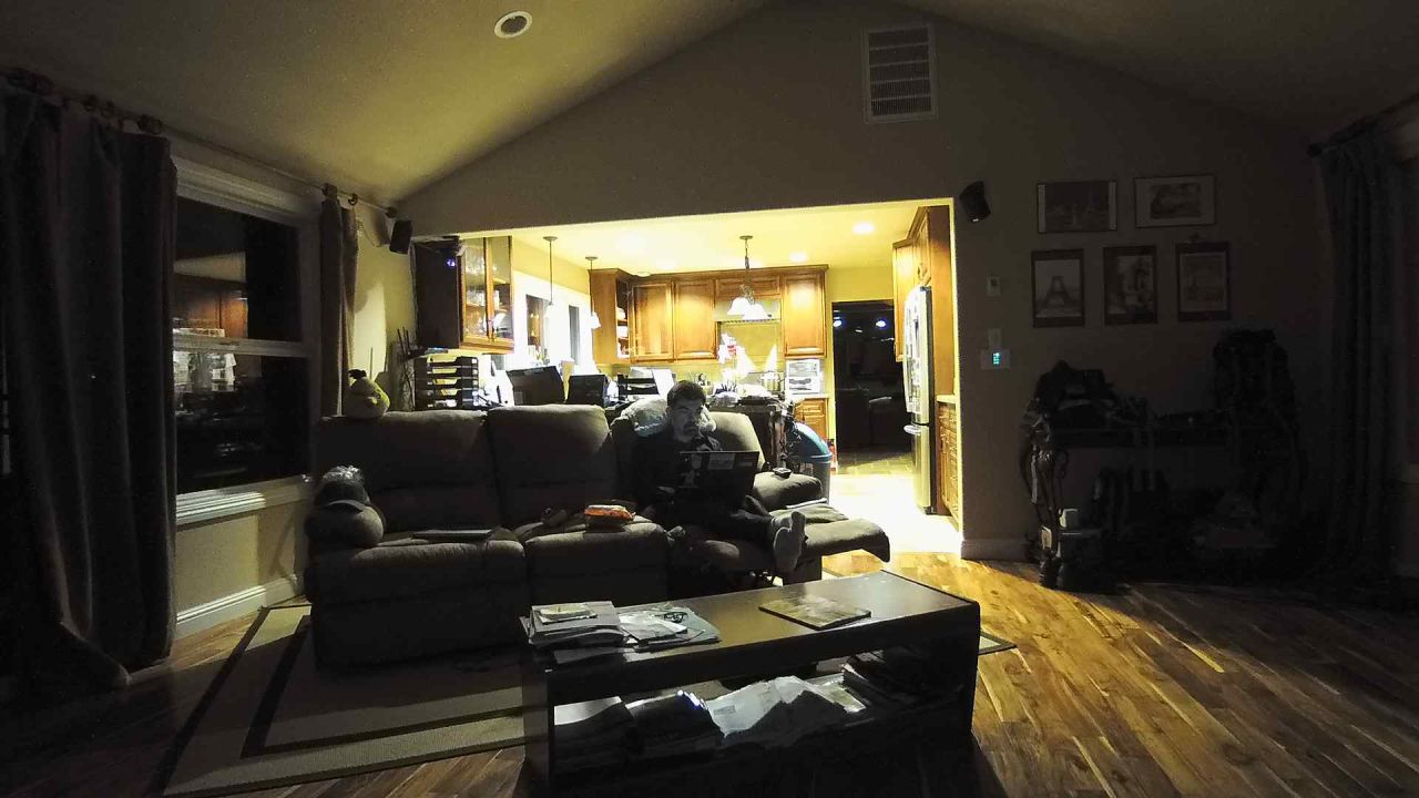
The viewing anble is pretty narrow. That's either a good or a bad thing depending on your needs, but if you need wide, prever the NCM625GA if you can put it outdoors safely, or consider the foscam or a higher priced camera. The night vision is decent though:

The 1920x1080 shots are truncated to 1280 for display on this page
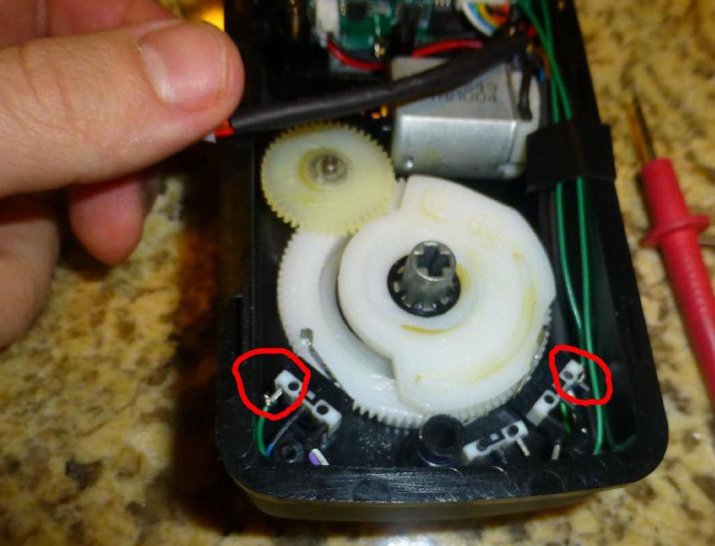
My camera was giving blurry pictures because the lens was mis-adjusted. I had to open it up and readjust the lens for the picture to a bit more clear.
Like the NCM625GA, it now comes with firmware that works fine with linux and any operating system, and the android app gets the camera working in no time after you scan the QR code.
Wansview K1
This is wansview's smaller version of the NCM625GA that adds temperature and humidity monitoring while removing the motorized base.
Please read the Wansview Q1 review for details on magic URLs to use, and firmware updates.
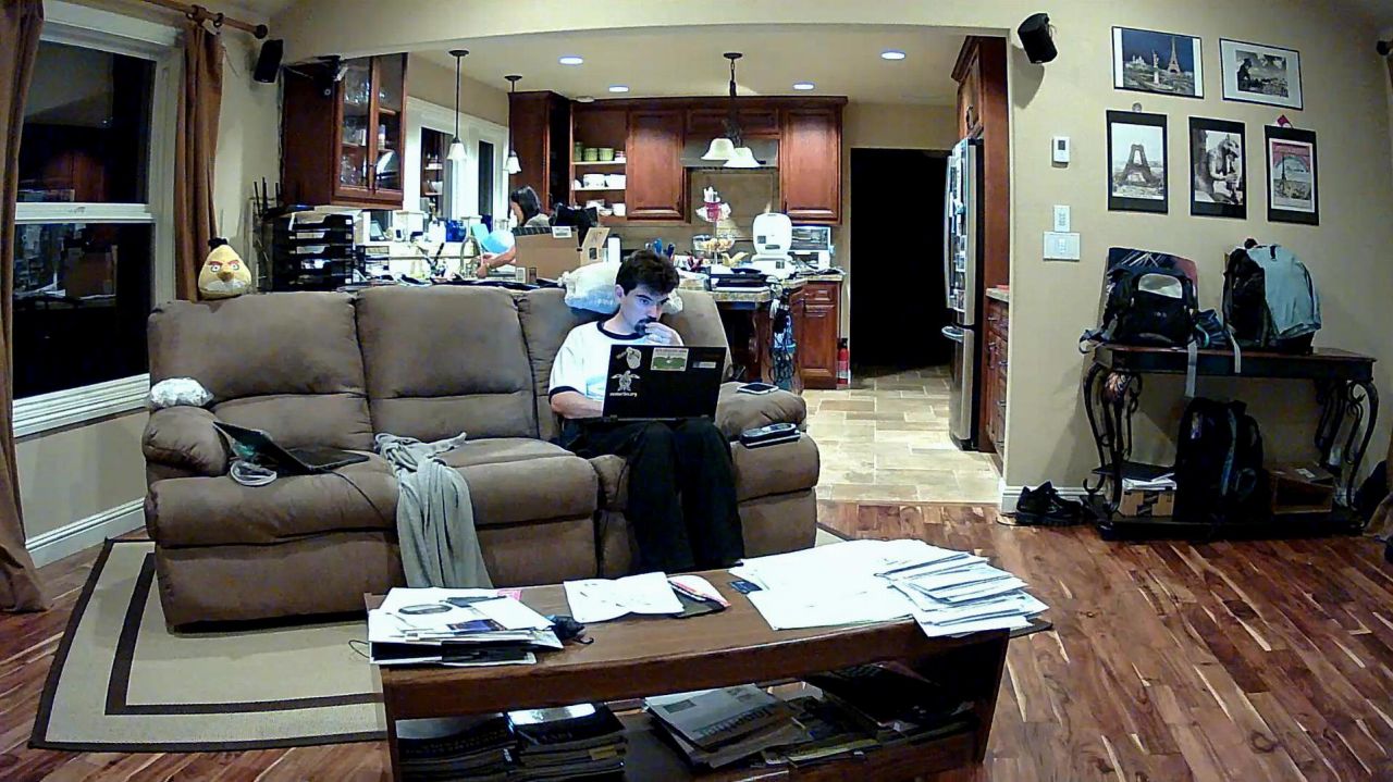
It's a great little camera. Just like its big brother, I installed the recommended iSmartViewPro on android, scanned the QR code on the back of the camera, and had it working instantly. The picture quality is very good and this is the widest picture of any camera I've reviewed so far (even if it comes at the price of barrel effect).
Please refer to my Wanview NCM625GA review for configuration details. The only real downside is the placement of the ethernet jack, making it hard to fit some ethernet cables unless you remove the flexible sleeve, but that's a manageable problem :)
If you have firmware 0.39 or 0.40 and install this firmware patch I got from Wansview (via the web upload interface), http://ipaddr/mjpeg/snap.cgi?chn=0 now returns a proper Content-Type: image/jpeg header and will work with Zoneminder and other software that expects a jpeg. If your firmware is 0.41 or later, it should just work without the patch.
It is the best 1080p camera you can get for that price, I'm quite impressed with it.

The 1920x1080 shots are truncated to 1280 for display on this page
Wansview W2
This is wansview's smaller version of the Wansview W1 (NCM751GA). It's much smaller, cheaper, and otherwise short of onboard storage, it's really identical in functionality, including the narrow 6mm lens, which may or may not be good depending on your application.
Please read the Wansview Q1 review for details on magic URLs to use, and firmware updates.
My camera shipped with firmware 0.42 which supports http://ipaddr/mjpeg/snap.cgi?chn=0 out of the box with a proper Content-Type: image/jpeg header and will work with Zoneminder and other software that expects a jpeg.
This is definitely a good alternative to the Foscam FI9900 if you are ok with a narrow lens in exchange for better firmware froma better company. However I'm not going to lie, the picture is not ultra sharp. It doens't look blurry but it feels like the sensor is not truly 1080p, or something is robbing a bit of resolution or sharpness.

The 1920x1080 shots are truncated to 1280 for display on this page
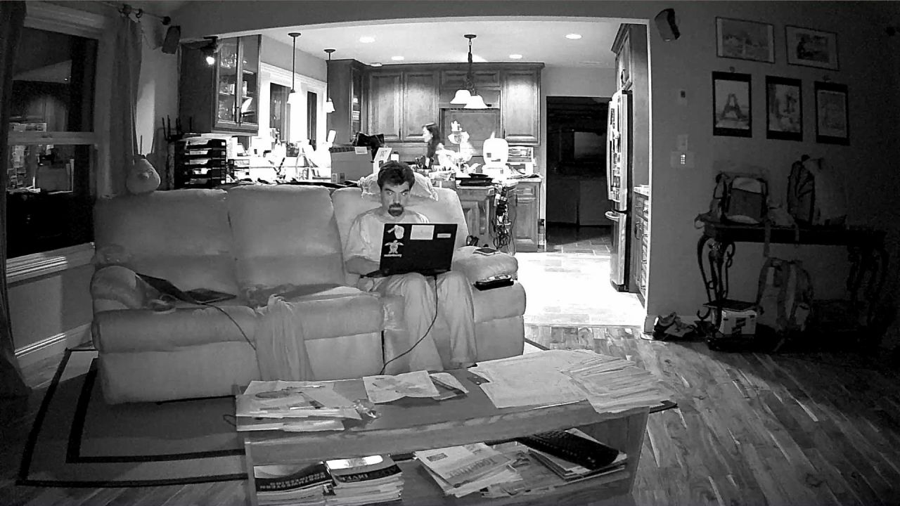
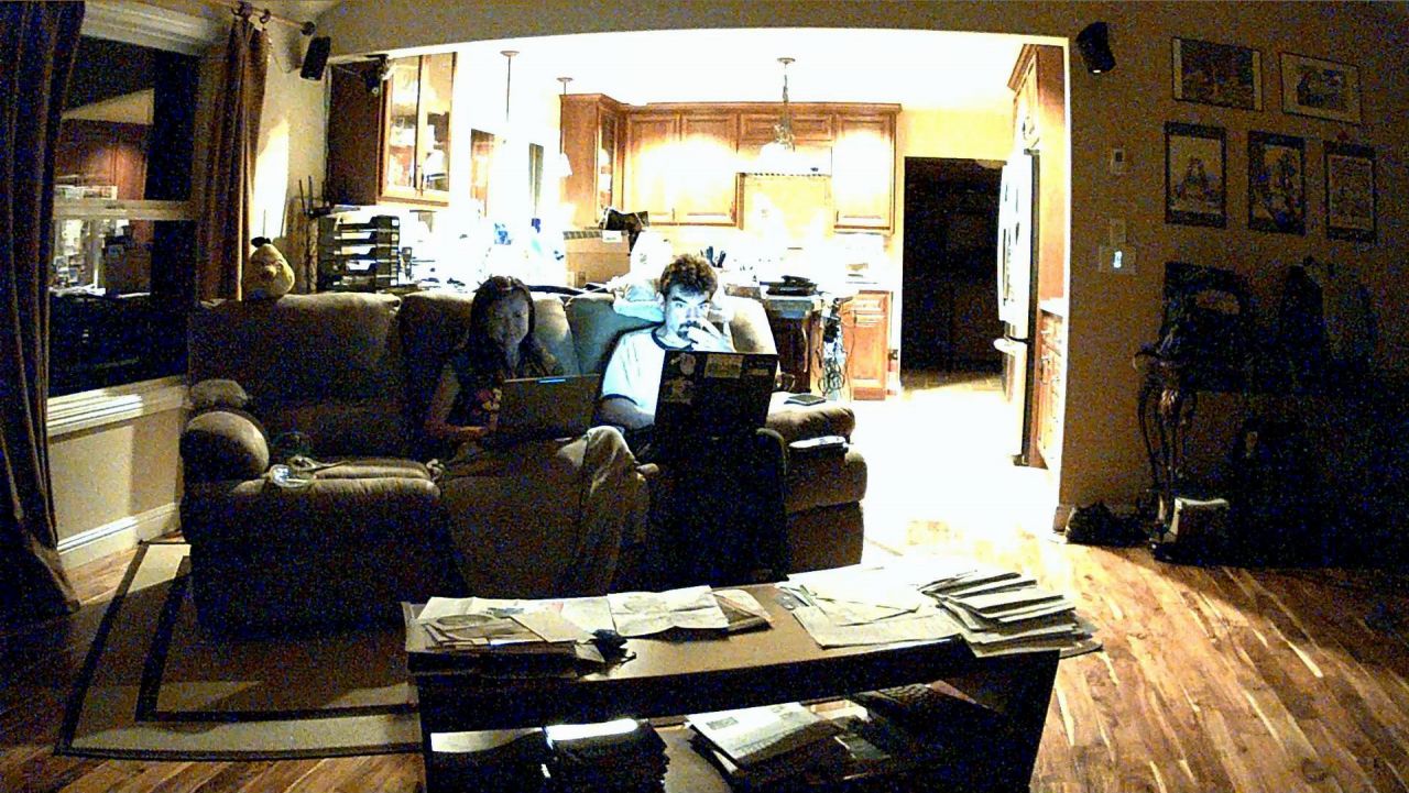
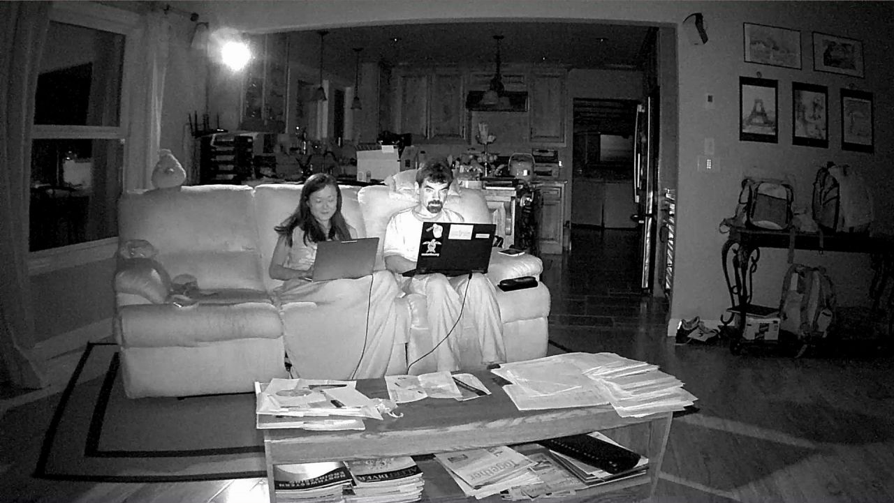
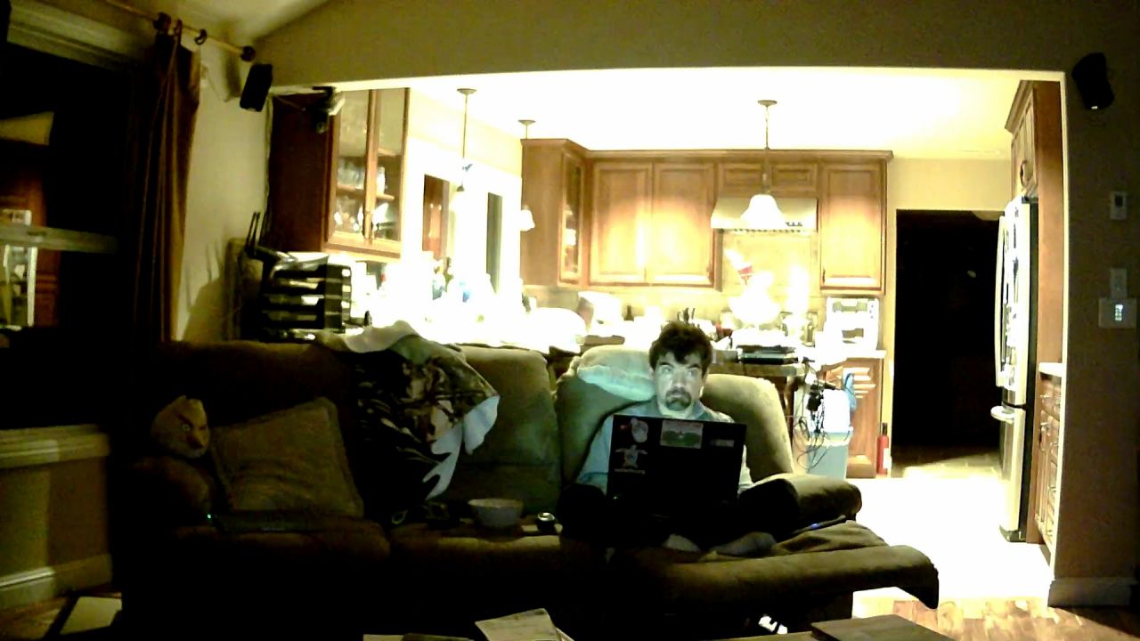
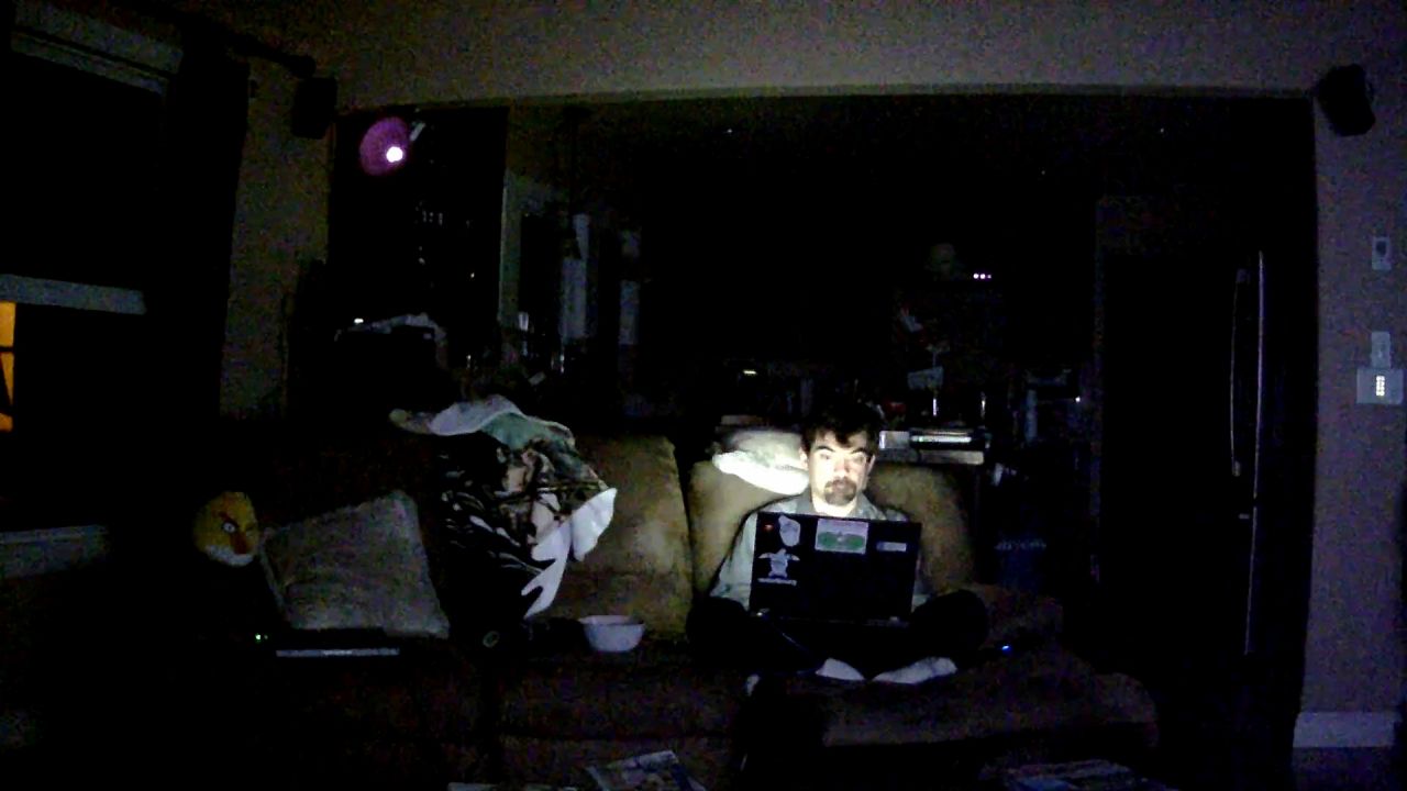
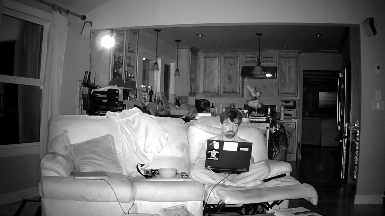
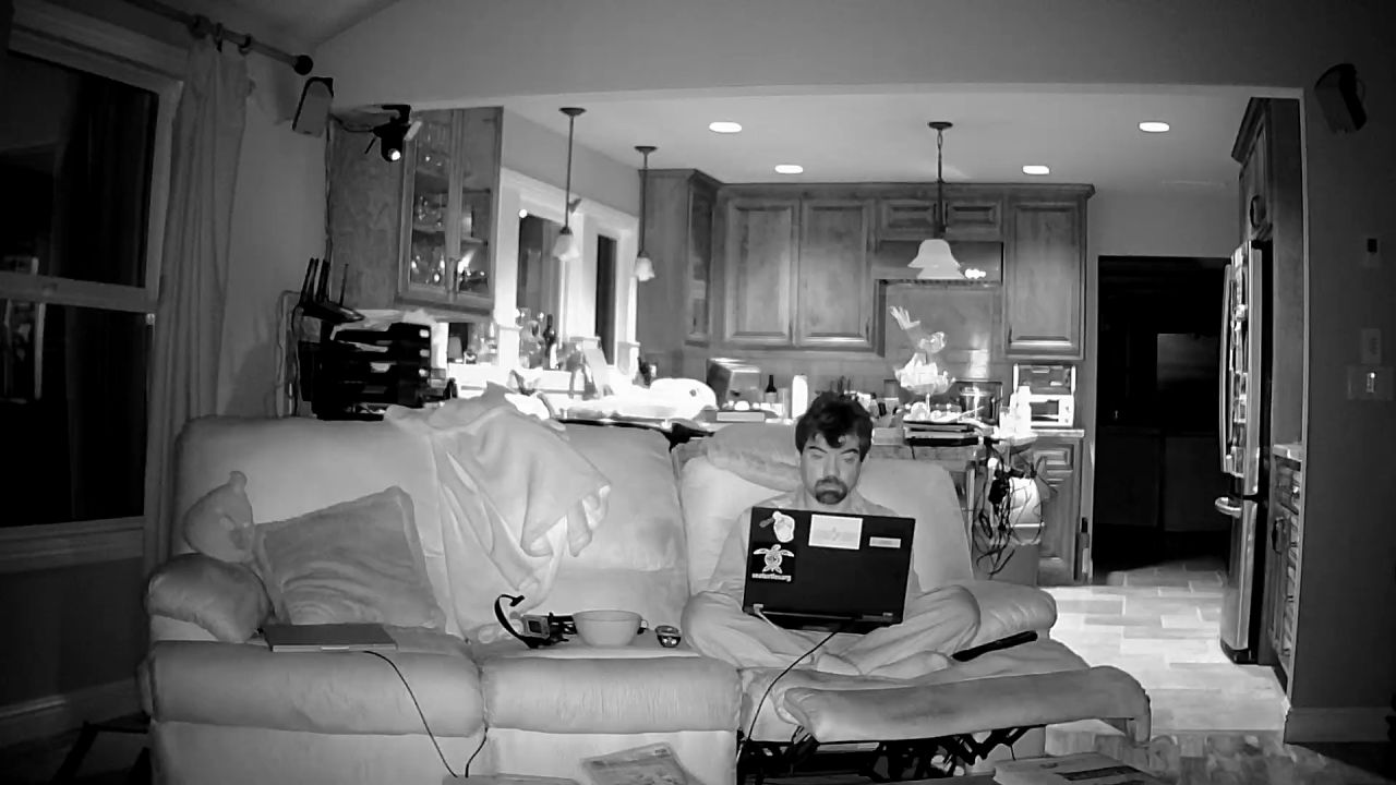
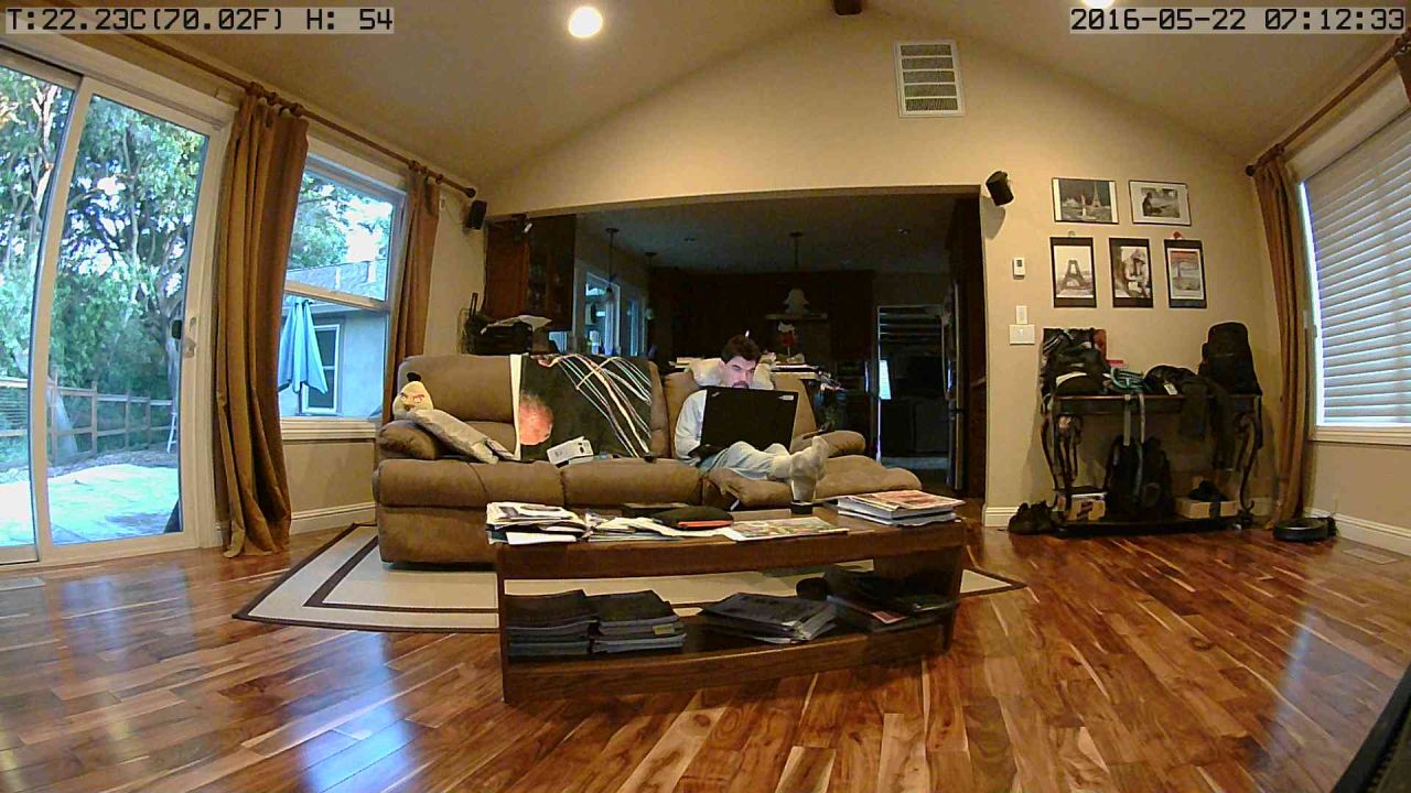
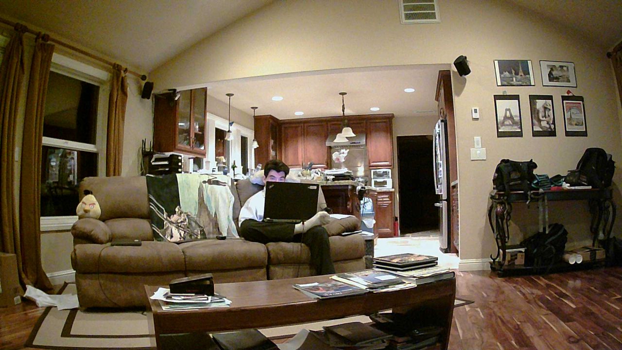
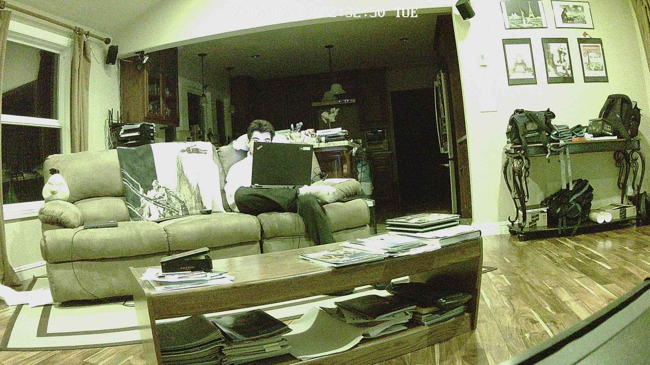
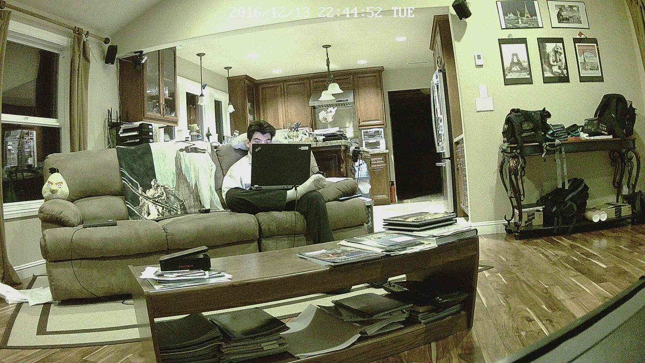
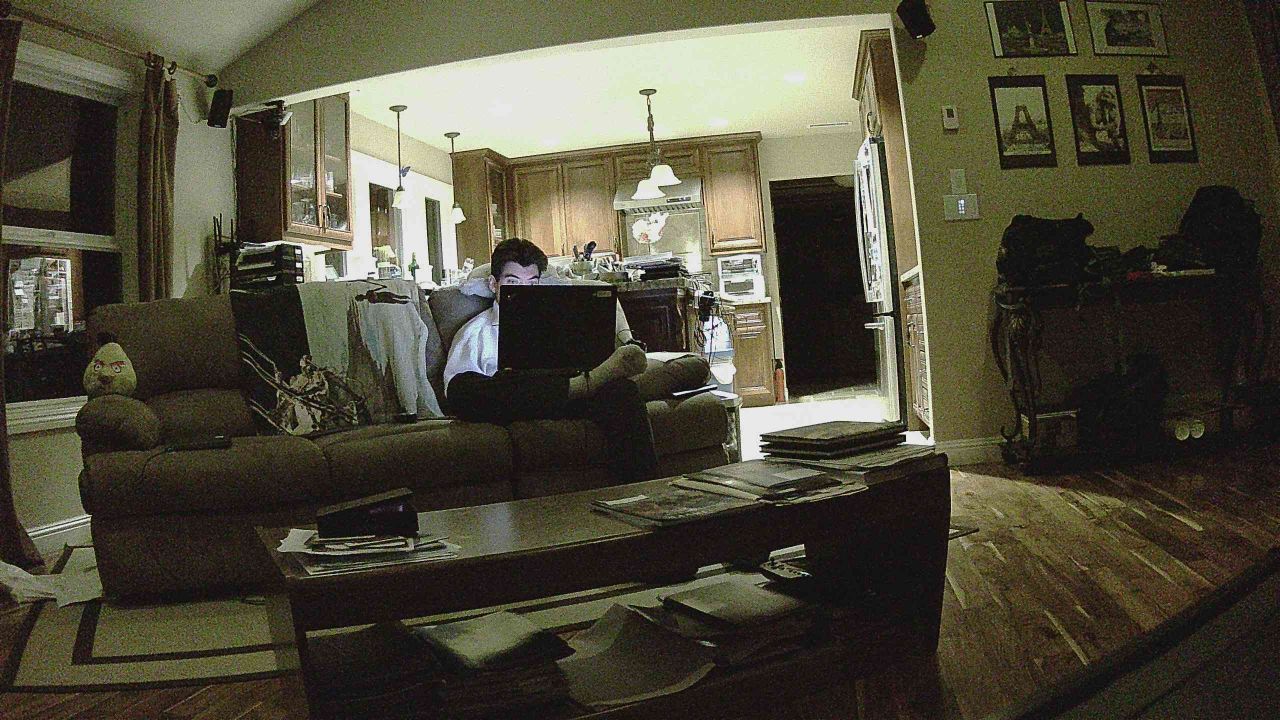
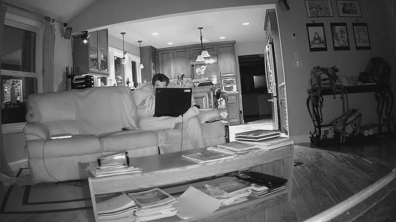
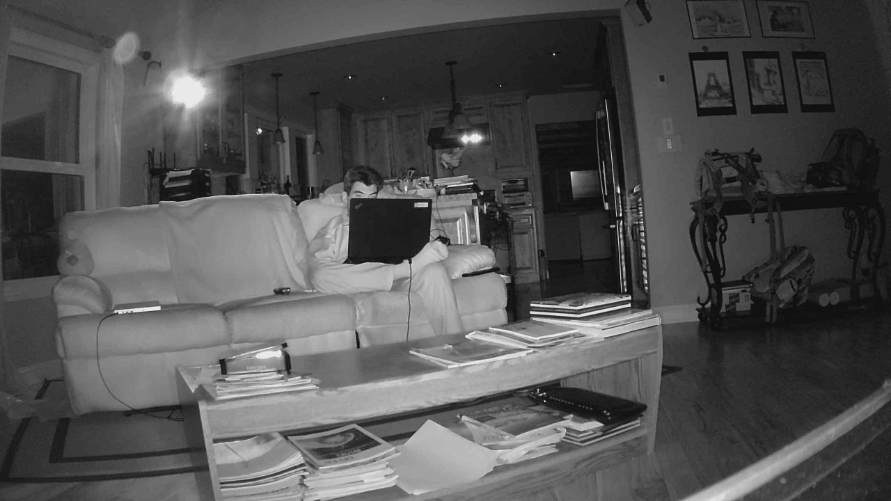
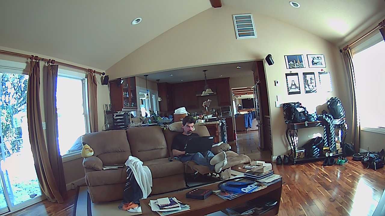
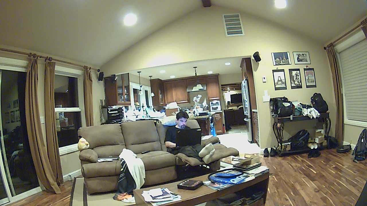
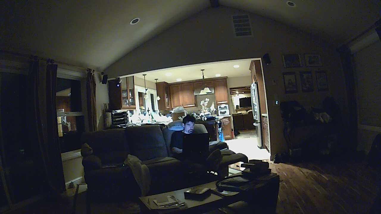
Wansview Q2
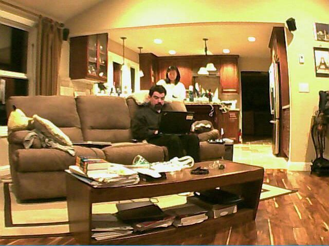
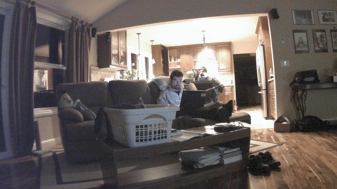
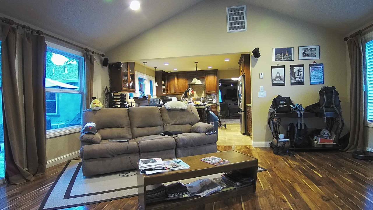
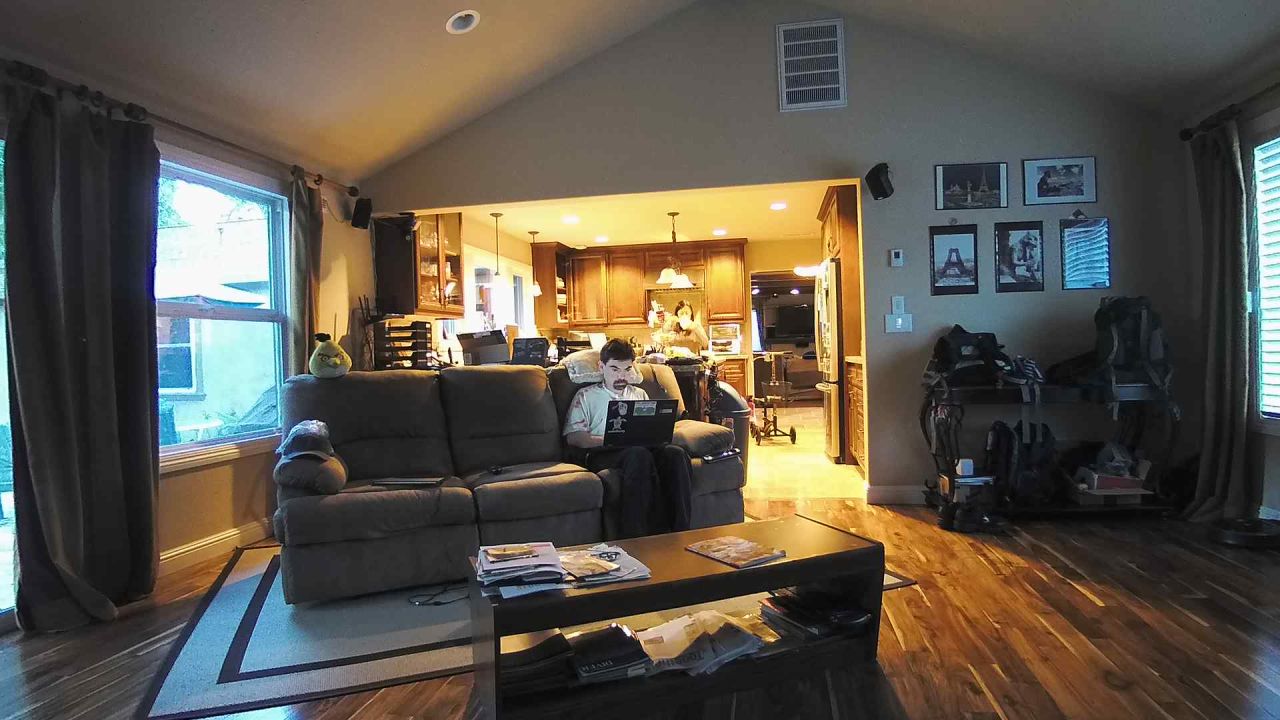
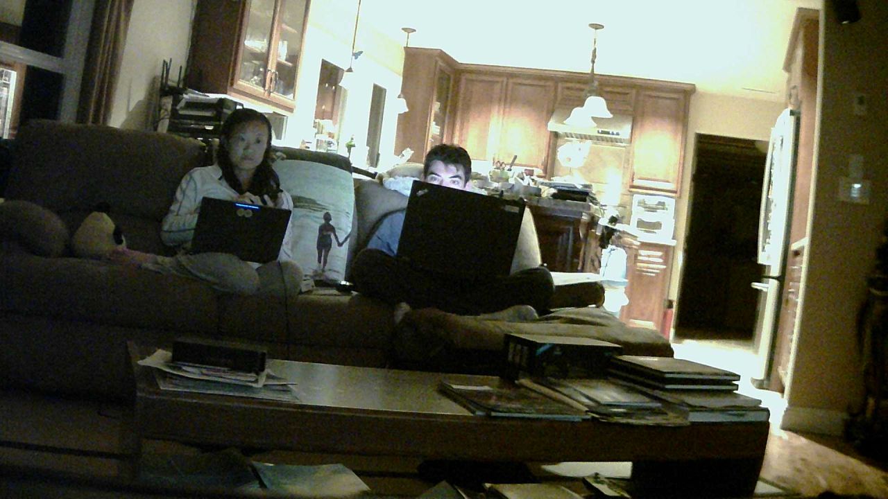
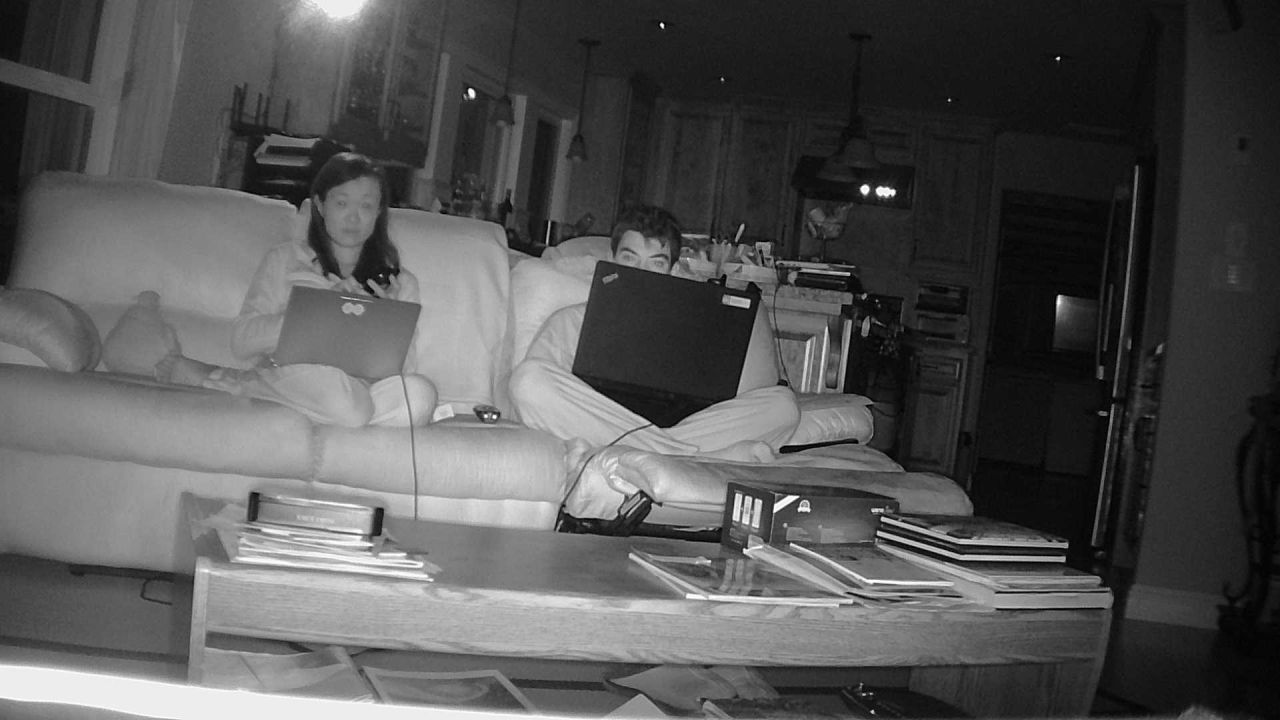
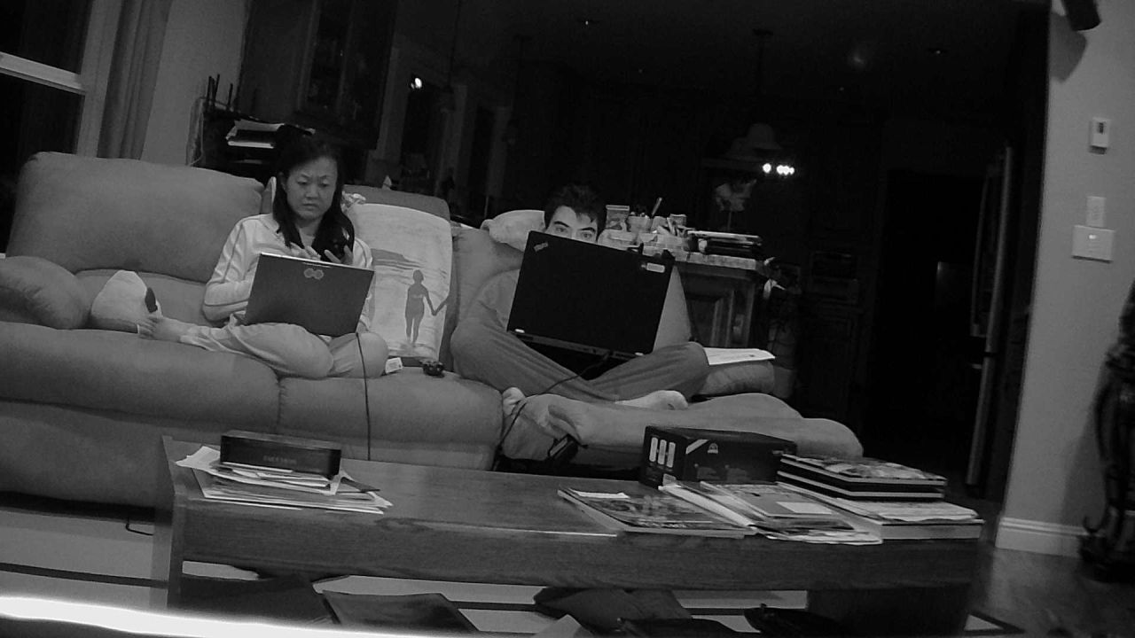
I really liked my Wansview Q1, it was a great motorized camera with good wide lens, for a good price. The Q2 is a similar camera that's just a bit smaller, and offers similar performance. At the time I'm writing this, they are similarly priced. The Q1 is tiny bit bigger and offers a it more I/O. The Q2 is smaller and white if you prefer that over white, but the more important difference is that the Q2 has a lens that is a bit wider, so you will see a little bit more of your room with it than with a Q1. On the minus side, I found the picture less sharp on the Q2 than the Q1. You can compare the screenshots for yourself.
Please read the Wansview Q1 review for details on magic URLs to use, and firmware updates.
My camera shipped with firmware 0.42 which supports http://ipaddr/mjpeg/snap.cgi?chn=0 out of the box with a proper Content-Type: image/jpeg header and will work with Zoneminder and other software that expects a jpeg.
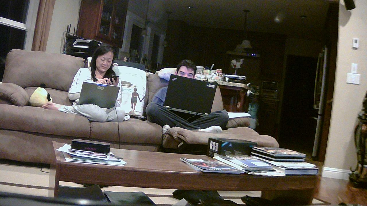
The Q1 picture is a bit more narrow and looks a bit more sharp

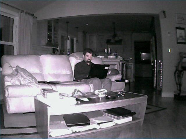
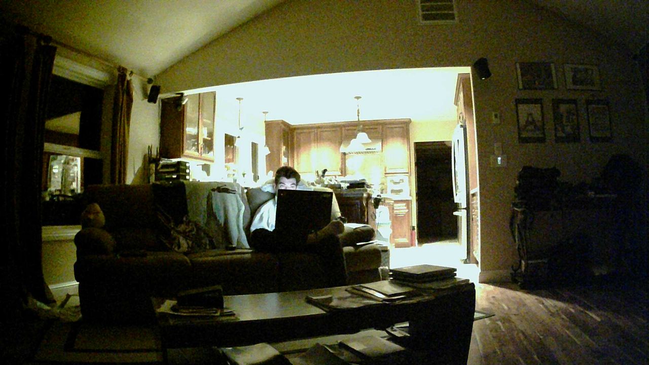
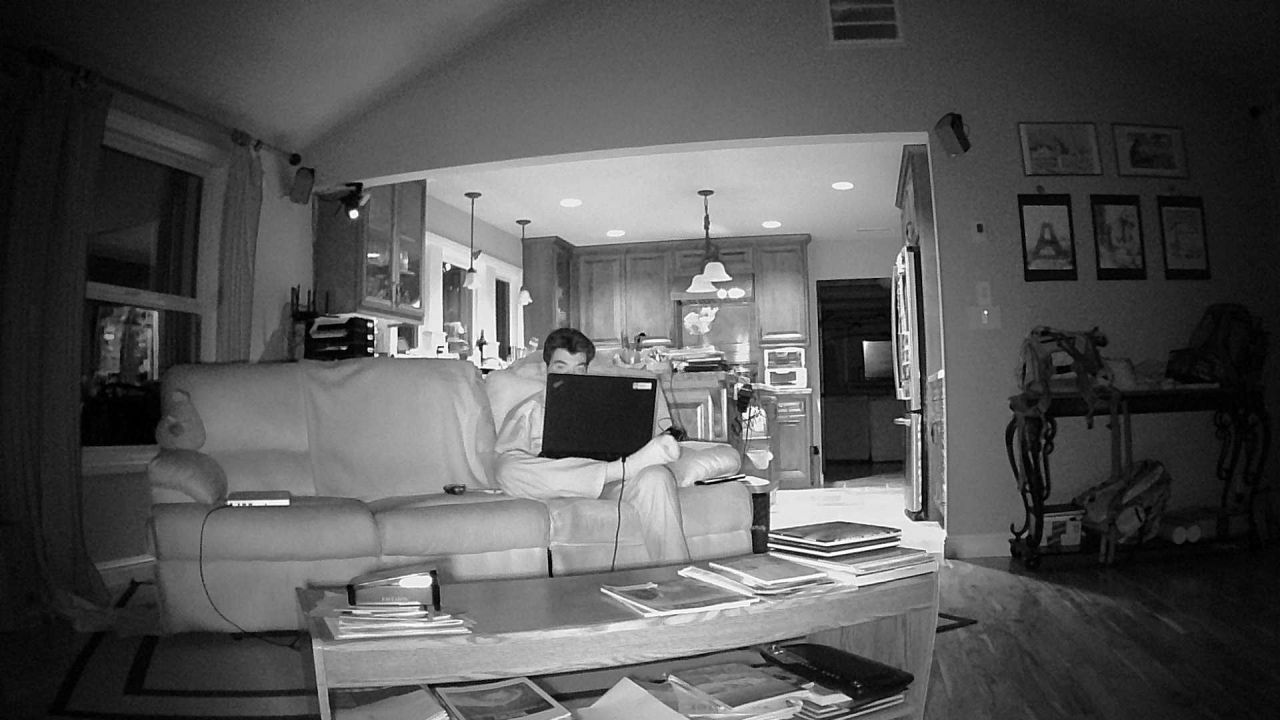
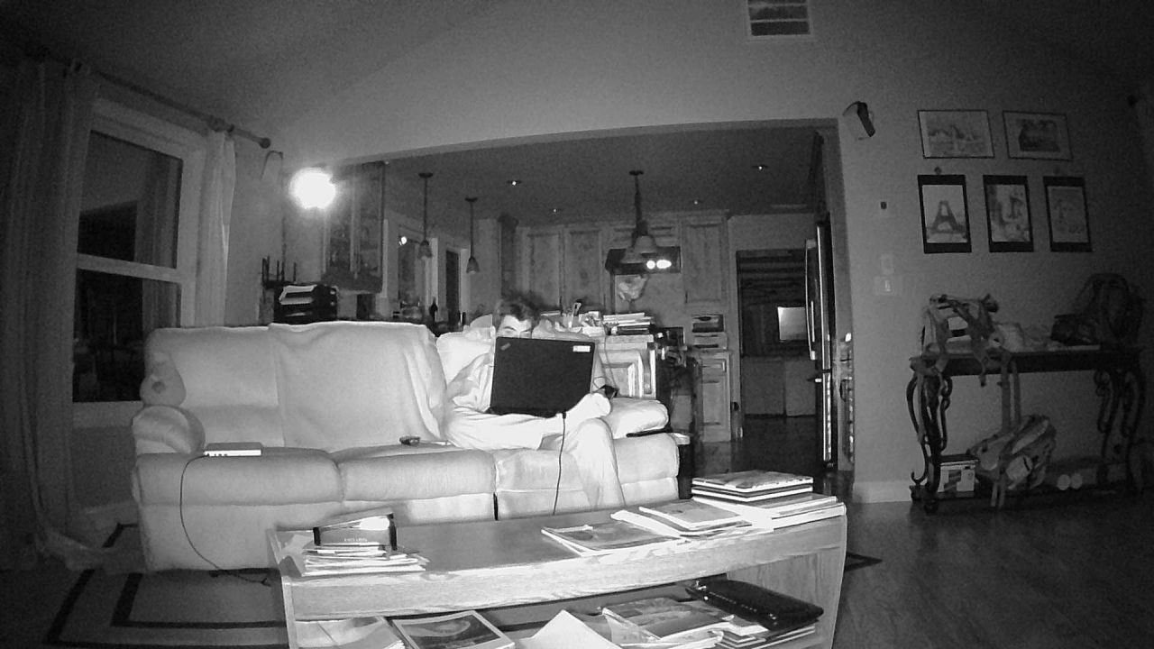
The Q2 picture is a bit wider and bit less sharp
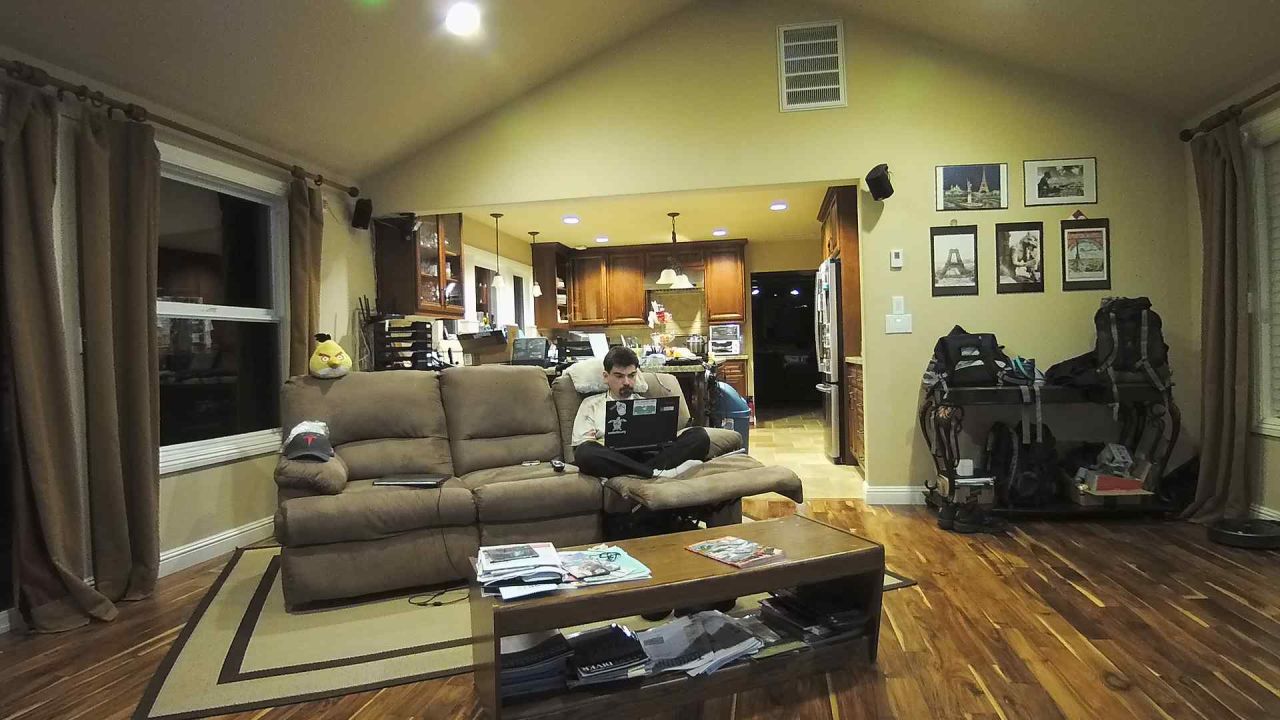
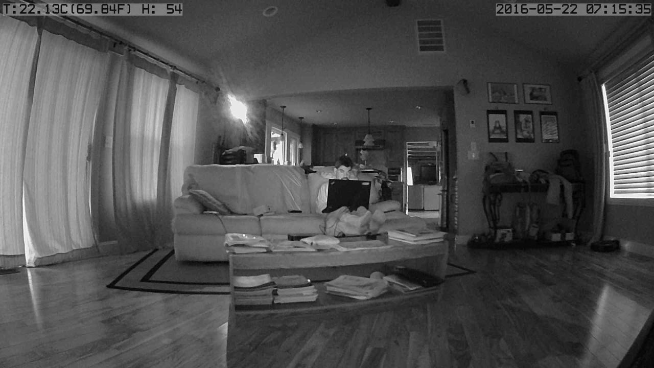
Here are the other Q2 screenshots, they look fairly good at night;
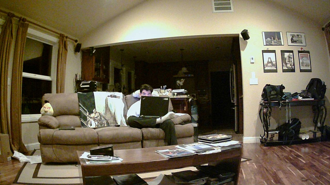
Reolink RLC-410
I tried a reolink since it offered 1440p resolution instead of 1080p like the wansview, and despite the low price, the firmware worked pretty well (no problems on linux/chrome), and http jpeg downloads work fine too, although the download URL is weird: http://192.168.205.206/cgi-bin/api.cgi?cmd=Snap&channel=0&user=user&password=pwd . Actually, let me scratch that, jpeg downloads work fine in a browser, but return a content-type chunked that does not work with software that expects a simple image/jpeg in return. As a result, zoneminder does not work with this camera unless you use RTSP which itself is full of problems since it can easily push data faster than zoneminder can process it, yielding broken frames.
Setup was a breeze, the one downside is because it's a PoE camera, it does support 12V input, but it does not ship with a 12V power supply. Thankfully I have a drawer full of those :)
The default picture was way too bright (over exposed) and the sharpening was turned up too high, making the picture grainy. On the last picture, I turned the brightness down as well as the sharpening, and the results are better. The lens is about as wide as Wansview Q2. *Update* a firmware update seems to have dramatically improved the picture quality, which to be honest, was pretty poor. The screenshots below are the old picture quality, I have not had the chance to get shots with the new firmware yet since my camera is installed outdoors at the moment.
Here are screenshots (resized to 1280, but you can click on them to get the full original size). Again, these are very poor quality and a new firmware fixes those:

Wansview K2
This is wansview's smaller and cheaper version the K1. It's about as barebones as you can get for an IP camera: $30.
This camera is about half the size of the K1 (on top of being half the cost), and is wifi only. Setting it up is interesting as it doesn't use the typical methods of acting as an access point that your phone connects to, or having a side channel to configure it via bluetooth (probably for cost reasons). Instead you use the wansview smartphone app to enter your access point details and it'll emit a loud sound that encodes the Wifi name and password, which get picked up by the camera's microphone. That's a pretty cool hack :)
To be fair, setting up the camera is a bit blind, you only have 2 LEDs close to one another and you need to send the sound sequence at the right time and hope it works, or reboot and try again. Also, don't forget that if you send a 5Ghz network, it won't work since the camera only does 2.4Ghz wifi. It worked for me on my second try, but basically you're working kind of blind. This may get a bit annoying if you're having problems setting it up, and in that case spending more money on the K1 may be a better option.
So, for that limited price, you still get most of the typical wansview interface without any sdcard or recording support, but you can tell the CPU is slow. It's slow enough that you have to wait for the web page to load, and also slow enough that a reboot takes a while. Last, but not least the picture is only 720p, not 1080p, and when comparing a downsided picture from a K1 and a native 720p picture from the K2, the K2 picture is not as sharp but still very usable
It's far from a perfect camera, but again, you only paid $30 (my favourites from Wansview are definitely K1 and Q1). If you want a camera that's more capable, the K1 is a very good small camera, so get that one instead. The choice is yours :)
Here are the screenshots in native 720p:
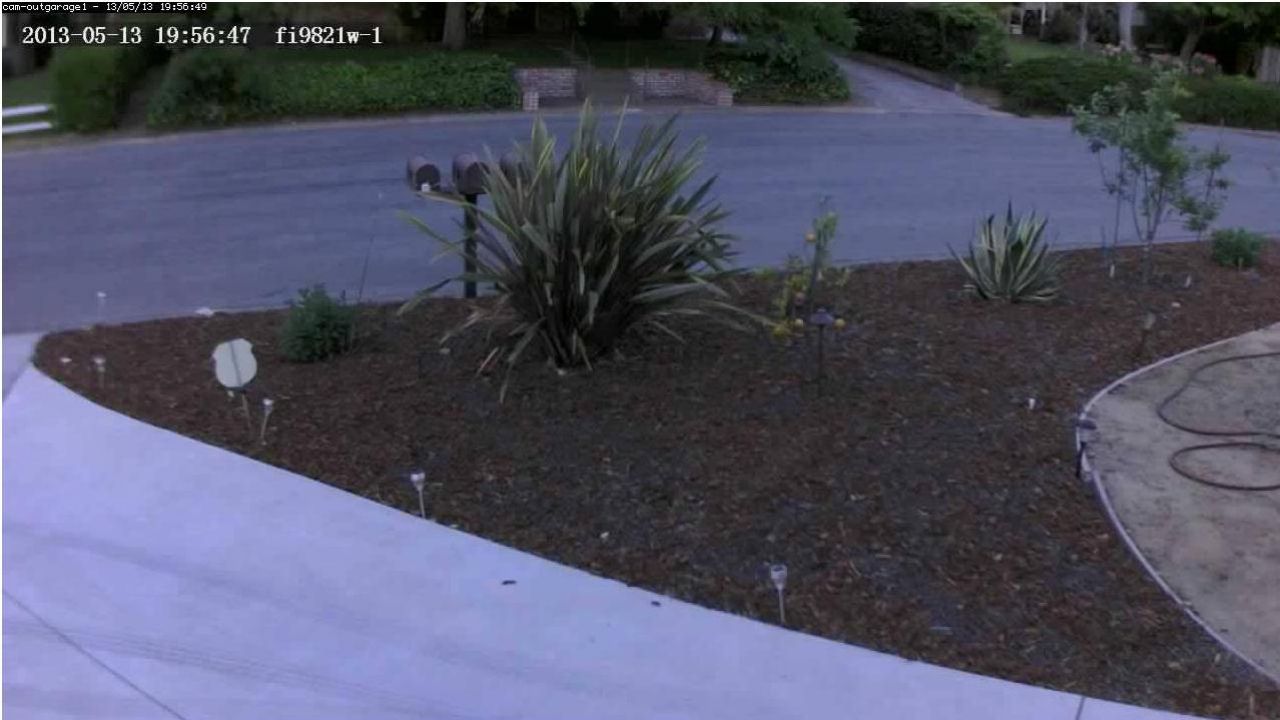
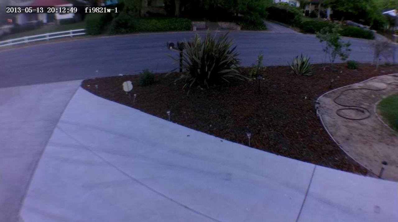
Using cameras outdoors
I'm in California, so we don't have extreme weather. I use indoor cameras outdoors because the choice of good outdoor cameras with wide angles and reasonable pricing, was limited to say the least. This is probably an example of what not to do :) (but it's been working fine for over 2 years, and as luck would have it, my real outdoor camera is the only one that died after 2.5 years of use).

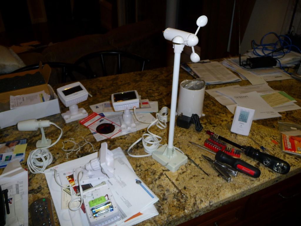
Foscam FI9821W and Zavio F3210, along with an IR booster for better distance vision at night with the Zavio

we don't exactly have harsh winters here, or really bad rain, so part of my equipment is just outdoors under the gutter

I then have ethernet and power going in my yard to the malibox
")
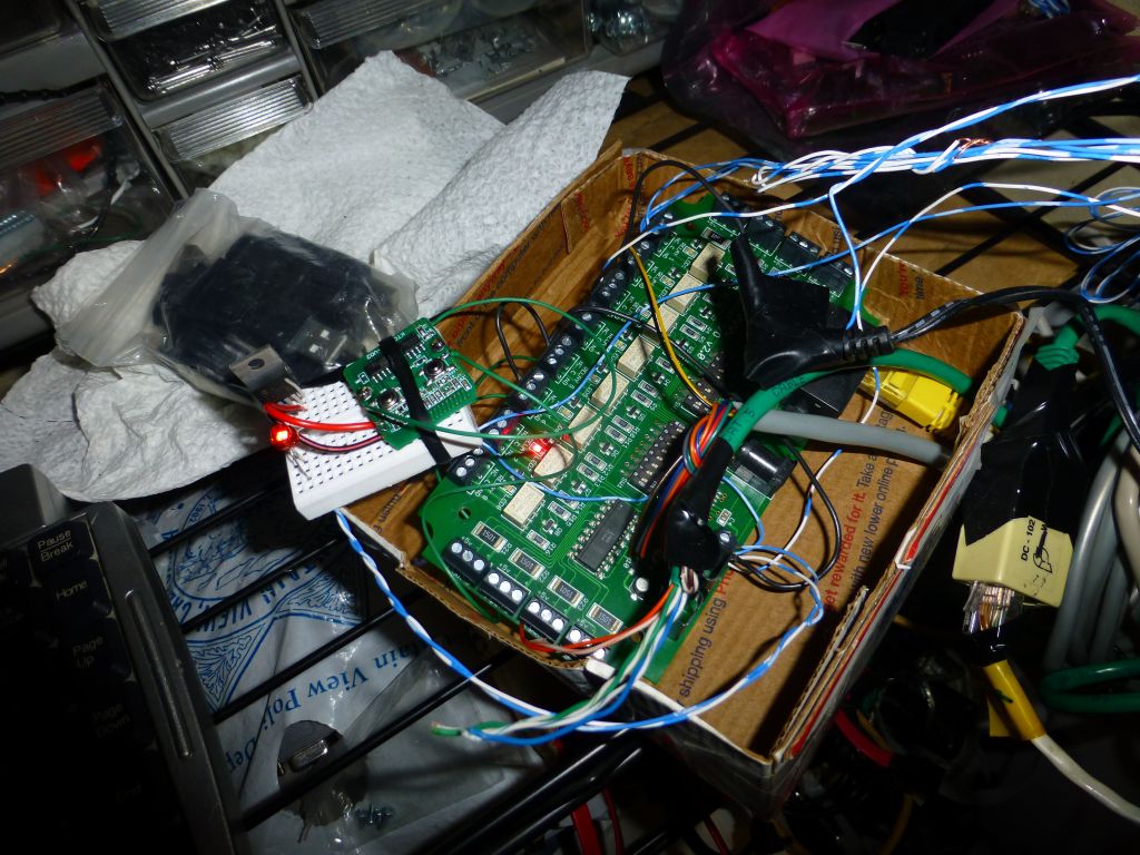
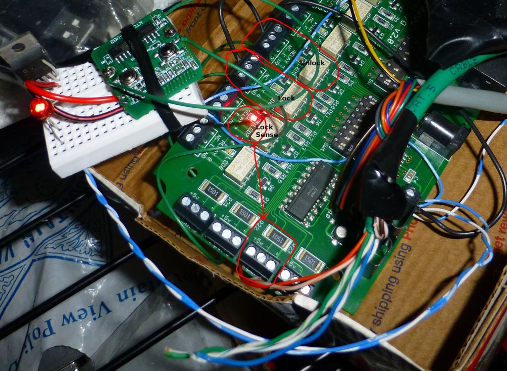
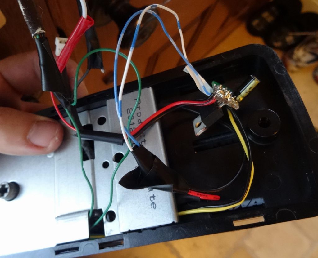
I do use a waterproof box for equipment outside (includes an insteon iolinc to control the mailbox and flood light if you open it)
, and 4 IP cams")
very tight fit, but I used a 7A 12V power supply to power the gigabit switch, floodlight (12V LEDs), and 4 IP cams
")
this should take care of any mailbox thieves :)
|
|


")