Well, the 5th (and maybe last?) edition of my LCD outfit was a lot of work compared to the previous ones, it took 1.5 years of work during covid to make it happen. Version 4 was described here.

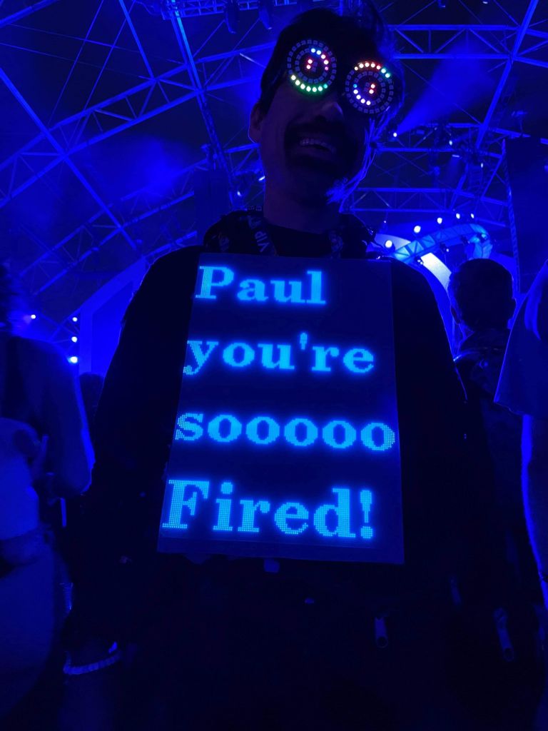
end result after 1.5 years of work
Move to Raspberry Pi
The v4 outfit was 64x96 resolution (3 P4 panels of 64x32), while the new v4 outfit changes to 128x192 (3 P2 panels of 128x64), or 4 times more pixels running in the same exact footprint (my body size, which ideally remains constant :) ).Because I now have 4x more pixels, and that would have been too much for an ESP32 or teensy (before teensy 4, which could have done it, but it lacks wifi), I had to switch to something with more memory and horsepower, I went with rPi and Henner Zeller's rpi-rgb-panel library, which also supported more panels like mine that had an FM6126 or FM6127 chip that required a special init string.
The other reason for rPi is that to get a high refresh rate and avoid visible refresh bars when taking pictures with cameras, it was better to run the 3 panels on 3 different channels to give them maximum refresh rate (300-400Hz is possible that way), which is supported by that library, using the active-3 board.
So, easy, I just have to port all my code from arduino/ESP32 to rPi/linux, right? Damn, that's actually a lot of work, and I didn't want to do this, so I was able to do something better, I found ArduinoOnPC, and was able to fork and modify it to add Framebuffer::GFX support and added 3 display outputs:
This combined work allows running my arduino code on linux, mostly unmodified, which means it runs on rPi. Then, the FastLED_RPIRGBPanel_GFX glue driver I wrote to make rpi-rgb-panel compatible with FrameBuffer::GFX, allows running all my 2D code, unmodified and have it sent to RGBPanels through the rpi-rgb-panel driver, I'm glad I didn't have to write :)
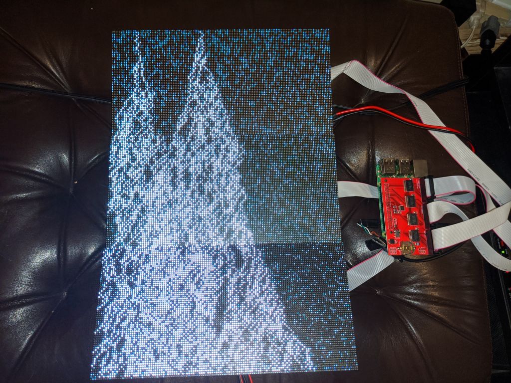
So, this is what the prototype looked like now 2 years ago:
I ended up writing this page explaining how others can do the same (run their arduino code on linux). On the way there, I took a small detour, built some RGBPanel frames with "excess panels" (those cost $50 a piece, I have over $1000's worth, ouch), and wrote this page about it: RGB Panels, from 192x80, to 384x192, to 384x256 and maybe not much beyond
")
ok, that was a nice distraction :)
In the process, I fixed a lot of bugs in all the 2D code I had when I went to a 384x256 panel which obviously overflowed all code that relied on x and y being smaller than 256, and also blew up FastLED code that assumed that there could only ever be 64K pixels :)
While this was a big milestone and proved that my crazy idea running arduino code on rPi using my same 2D library, was possible, there was a lot of work left to do for my outfit, including changing all the code to deal with a much higher resolution, and days (yes days) of work finding close to 200 animated GIFs in the higher resolution, and rescaling them for my non standard 128x192 resolution. Also, all the fonts had to be changed, and a bunch of other stuff, which took months and months of work (all in all over a year):
So, this is what it looks like, ESP32 SmartMatrix 64x96, compared to rPi rpi-rgb-panel 128x192, triple channel. Some gifs, I found the exact one in higher resolution:


this gif was so cool, it's only with the higher resolution that I found out it was Pulp Fiction
Other gifs, I found a much better one:

Here is a good video showing the resolution difference between the 2 chips:
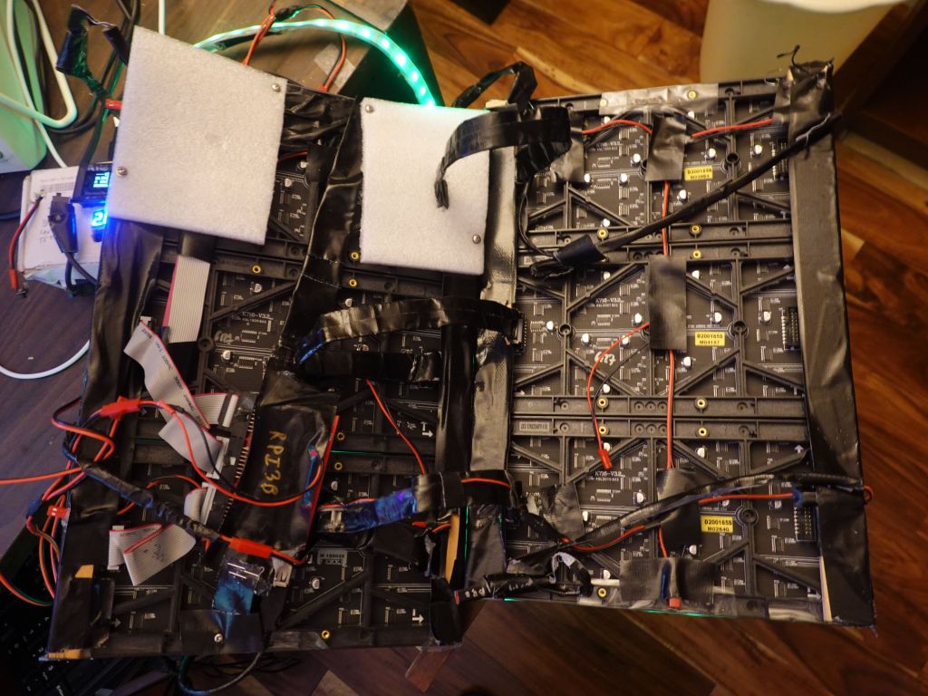
Hardware
The hardware got a bit more complicated, especially as my wiring wasn't giving reliable enough 5V power to the rPi causing random failures. Eventually I had to feed the battery voltage (16V) via a different cable and step it down to 5V/USB behind the panels to get full power to the rPi (otherwise when the panels drew too much from the main 5V source, it dipped it a bit too much and caused issues).It does not look great, it's meant to be serviceable and easy to debug, and that part is against my body, so people don't see it :)
For wiring reasons, I had a nice trick with the front panels would shift out bits, and I would send them to the back panels with ribbon cables. If you know how RGBPanels work, it does mean that a BCM plane meant to be displayed for an interval t1 in the front, ends up being displayed for an interval t2, when shifted to the back. Because of random luck of the order of BCM planes, it happened to work well enough with SmartMatrix, so it saved wiring for me (no need to splice the output to go to front and rear panels). Unfortunately with rpi-rgb-panel, the BCM planes are displayed in the opposite order it seems, so the output shifted on the rear panels, is visibly not good:

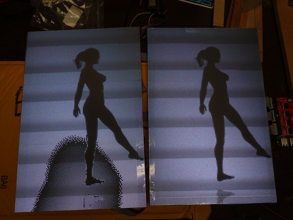
Unfortunately, there is no good fix to this outside of splicing cables, which I didn't want to do, so instead I slightly hacked the rpi-rgb-panel library to shift output bits twice. This is a bit wasteful for refresh rate, but things were fast enough with 3 channels, that I could afford the software hack and losing half of my refresh speed.
Another issue with the ribbon cables is that the active 3 board is wired to have the cable stick up (i.e. towards my belly). I worked with the nice folks at electrodragon to get bare boards without the connectors soldered and looked at how to best make it work for minimal height footprint. Bottom in blue is the original which sticks up the wrong way, upper right is what I would love to have but isn't possible because the traces on the board would have to be rewired (pin order is wrong when the plug is put underneath), so I had to settle with upper right, some angled connectors and I had to move the key hole from one side to the other for the cable to go in the right way.
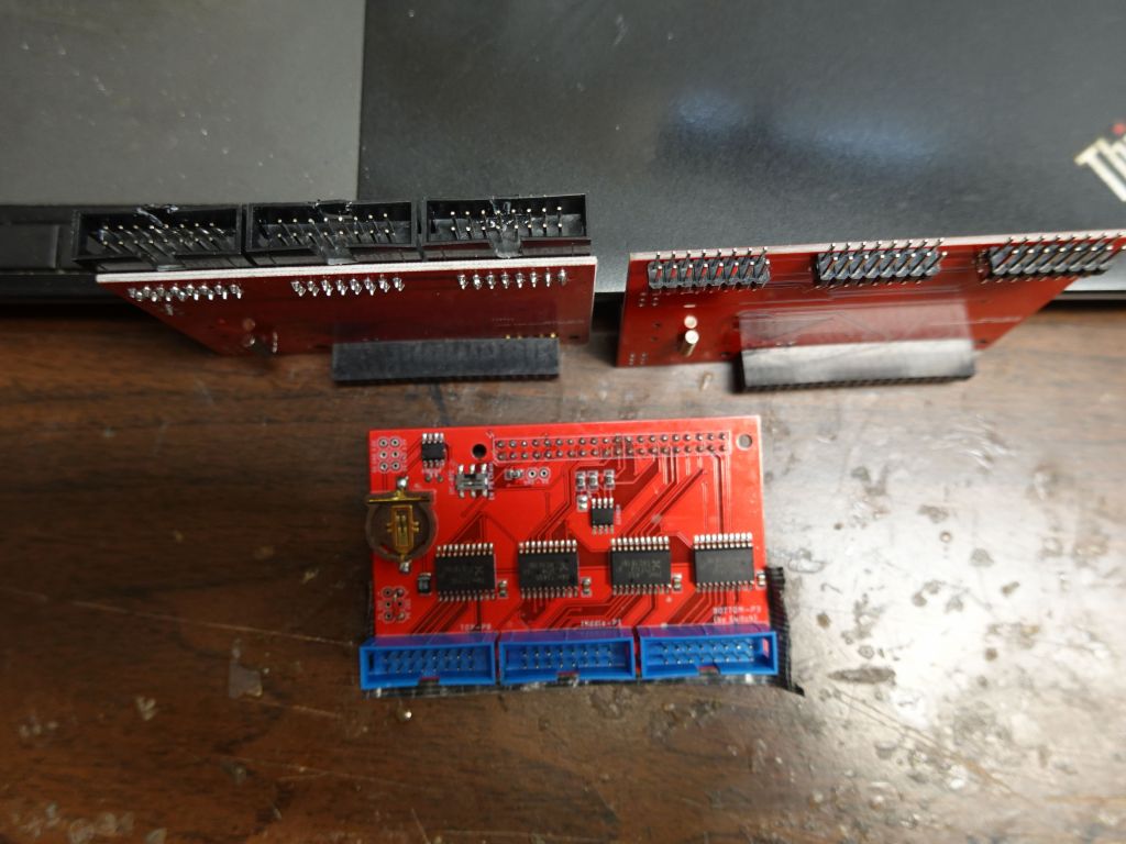

I really wish I could have done this, but the wire order would be wrong
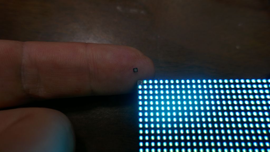
Then, I also had to protect the panels with my kitchen cutting board sheets that I've been using. It's not perfect, but they act as diffusers and protect the pixels a bit, because the P2 pixels are so small that they fall off if you look at them wrong:
Battery Use
The new setup uses a bit more battery, first because of the rPi, and also because the new panels use slightly more power, although not 4 times more because the pixels are 4 times slower, so the amount of light is somewhat similar. I had to upgrade my setup to allow adding a 3rd 80Wh battery for longer festivals (12 to 14H with 240Wh). With 2 batteries in the black box, I get about 8-9H.

ESP32 - rPi Integration
Because all my code was written for ESP32, including Wifi code that generated pages on the fly from code, thanks to https://github.com/distrakt/OmEspHelpers , and the ESP32 still runs the neopixels on arms and legs (plus IR input, although it's become a bit obsolete now), I took a very unusual approach of running my code on both CPUs a tthe same time.The ESP32 runs the demo, and blind outputs it to an RGBPanel that isn't there anymore. At the same time, its debug serial output is connected to rPi which reads it as a text input over a ttyUSB serial port. The rPi code can run in independent mode (where I control it via ssh from my phone, haha), or it detect a hearbeat from the ESP32 over serial, and read commands from the ESP32, including what demo to run. So, the ESP32 controls what demo is run, tells the rPi to switch to that demo and display to the RGBPanels. That makes the rPi a bit more than just a glorified graphics card/GPU since it generates what pixels need to be displayed instead of just being given a pre-computed framebuffer to display.
I had to make the code smart over time so that the rPi can connect and disconnect from the ESP32 and run independently if the connection dies (which it used to when I had power issues that cause the FTDI ttyUSB to fail routinely when running on batteries).
The rPi can also back-control the ESP32, so when I test at home, I ssh into the rPi, and the rPi uses the serial connection to the ESP32 to tell it what to do, or I can use the web server on the ESP32 and tell it what to do directly.
This means the rPi can work on its own without the ESP32 being needed, except for: - IR input (it's not really necessary, and linux IR code is very different, so it would be a full rewrite) - Wifi commands (none of Wifi code works on linux and would have to be entirely rewritten) - FastLED output would not work well on rPi since it's timing dependent, and also there are no IO pins left on mine with 3 channel output
If I were to re-write a lot of code to make wifi work on linux, that would make the rPi independent and not need the ESP32 anymore (except for the neopixel strips), so I just didn't bother. Also I can brag about having a dual CPU system with synchronization between the chips, which was fun to write and debug.
This bit of video shows how the 2 communicate:
Using Linux integration for development
There isn't much to say about this, thanks to my ArduinoOnPC work mentioned earlier in this page, the exact same linux code works on my rPi and my linux laptop, so I can write and debug my code on linux, which is so much faster.This shows an example of what it looks like:
Wifi and OmEspHelpers
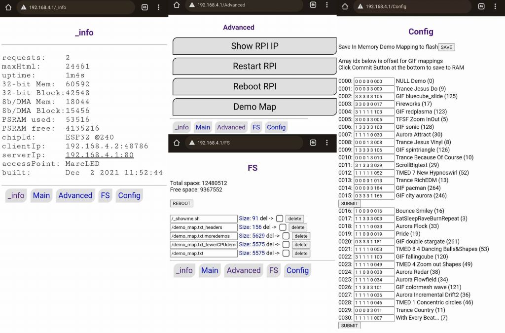
Ah yes, Wifi, that was a fair amount of code, especially on ESP32 where Wifi is more basic and can cause crashes if you get weird conflicts between interrupts, Flash (SPIFFS or FATFS), PSRAM, IRAM, and Wifi. After looking for an easy to use solution, I settled on https://github.com/distrakt/OmEspHelpers because I could generate the HTML pages from code (saving lost time to update the Flash FS each time, which is slow with 16MB, and not having to worry about syncing HTML tags between static HTML pages code).This is the end result, the main screen allows selecting which demos run (neopixel strips + main screen), at which speed, how bright:

there are over 200 2D demos to cycle through, some are machine generated, some are animated gifs
The diagnosis screens give more info on the device, and allow editing the config file that selects which demos run by default depending on the screen size, and whether 'bestof' is selected, or not. The config file also allows choosing the order demos run, in:
Demo of wifi:
Glasses
I got tired of the El Wire glasses, they were unreliable, got dimmer over time, required high voltage (I literally got shocked by that current when wires got frayed), so I got rid of them.I did try laser cut glass glasses, they look kind of cool, but they are big and impossible to fold.
I ended up getting neopixel glasses which had good battery life, but after I dropped them once, a pixel fell out, and that stopped the rest of the string from working. Thankfully I was able to take a spare neopixel from a strip and replace the missing one. I didn't have the right tools or skill, so I was not able to solder it, but I used glue and that worked too :)
![]()
![]()
LED Shoes
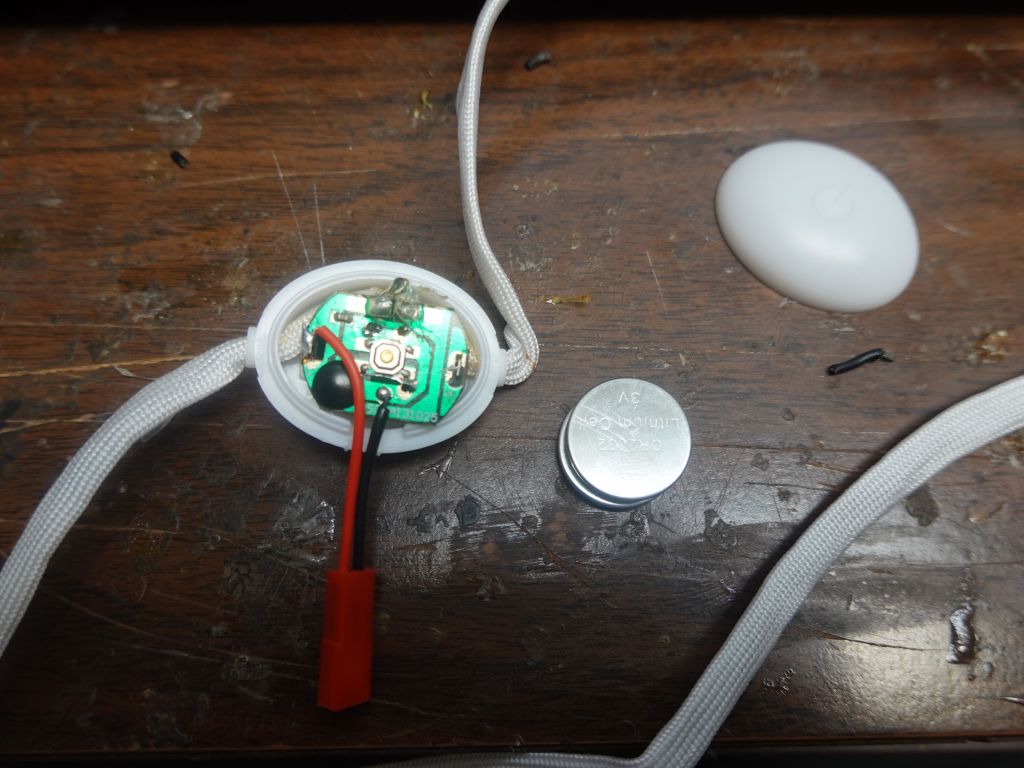
I've been using LED shoes since 2016. They're fun, but not that reliable: the LED strips keep breaking, if it's not the control module itself on occasion, and of course the battery is too small, which is why I wrote this page on how tohack/improve them, but that also makes them less reliable. I tried to find other options, but have not yet. I had a look at LED laces, and those are not very reliable either (or very bright). I tried to hack these to power from the power supply I added and upgraded in the shoes, but it was probably not the best idea:
Where is the code?
It's still the same code, and it's still there: https://github.com/marcmerlin/NeoMatrix-FastLED-IREnd result
I got everything somewhat working in April 2021 for a first show (about 1.5 years from when I started), and then worked through multiple electrical and reliably problems (including serial ttyUSB stability issues, and power issues I had to fix by adding a second higher voltage feed to the rPi). Also fixed sync issues between the chips and other improvements in graphics and menus. I considered V5 mostly done and reliable just in time for ADE 2021, EDC 2021, and Dreamstate 2021
I had the outfit mostly working (with a few occasional hardware issues) in time for Creamfields and untold in Aug-Sept 2021:
This even got me on Romanian national TV :)
I had fun at ADE also, and add time to make custom displays for specific events:


Solarstone looks better than his picture, haha
I have some early code that allows me to send text from my phone for special occasions, need to improve the interface: