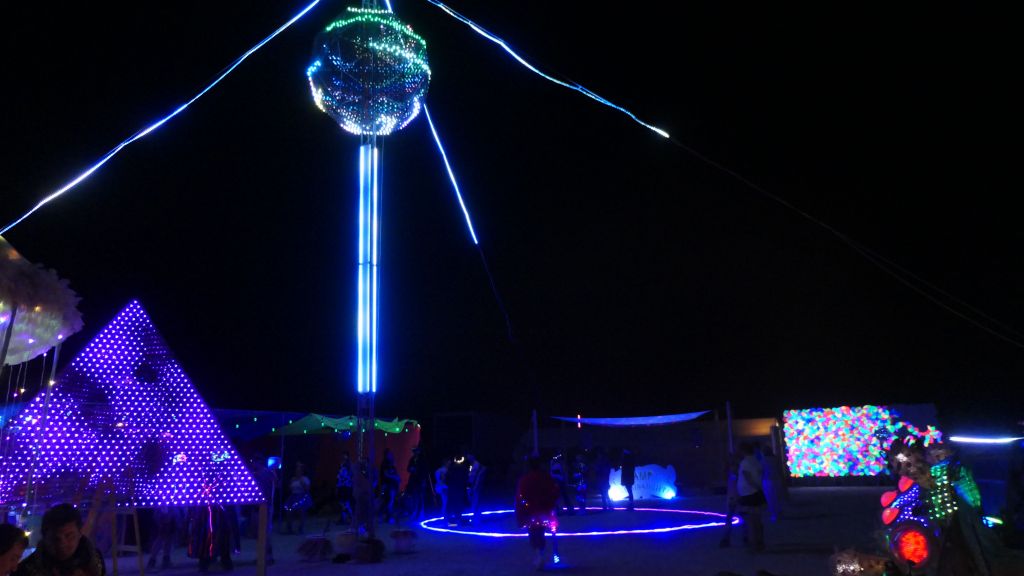
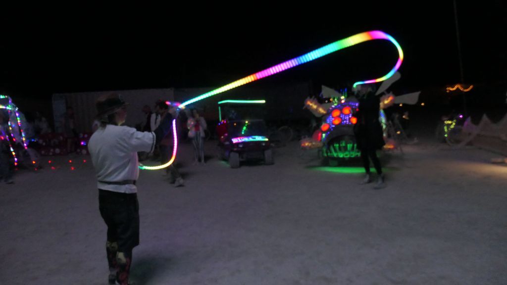
It was great to be able to attend my 3rd Illuminaughty LED Meetup, a great way to see other cool LED stuff built by like minded LED maker geeks. Several had really cool LED builds I had never seen and looked very well done, happy I got to see them :)
Just like last year, Illuminaughty was about as far across the playa as a camp can be, so it was nice when we arrived :)
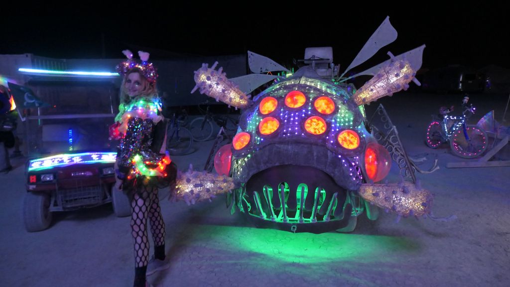
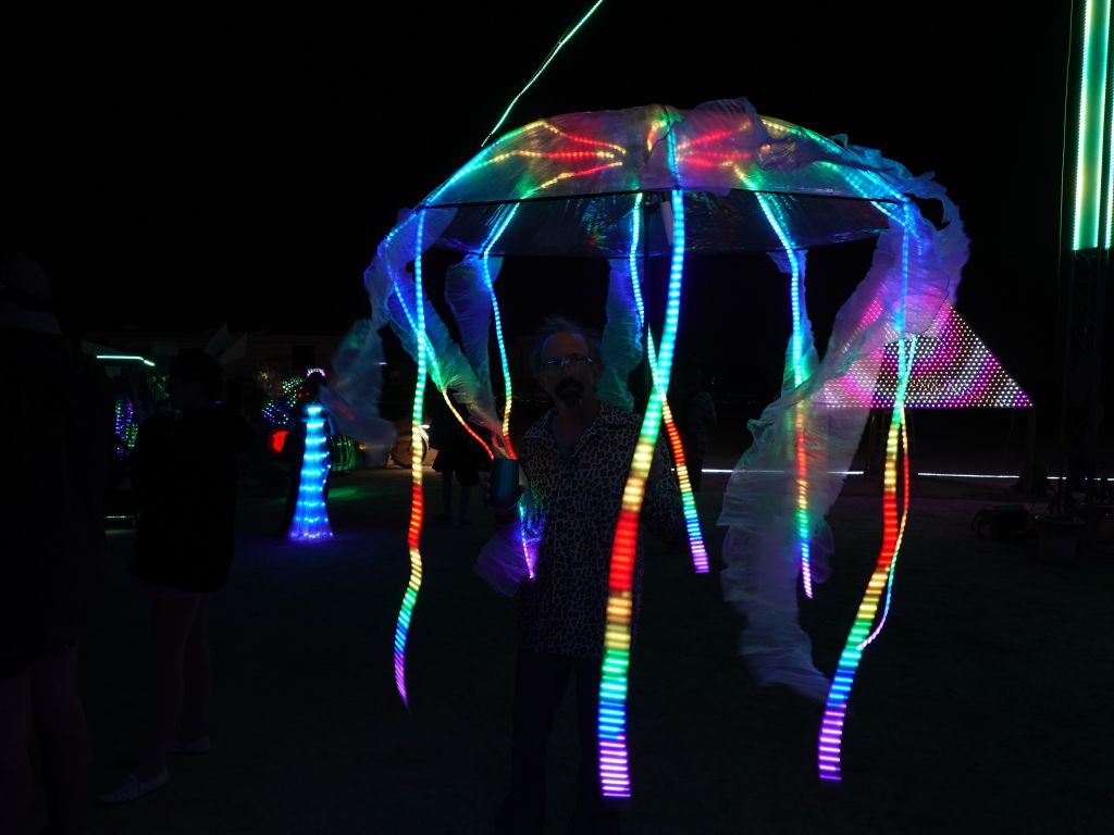
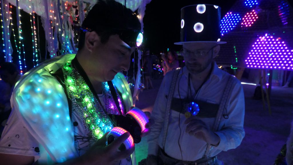
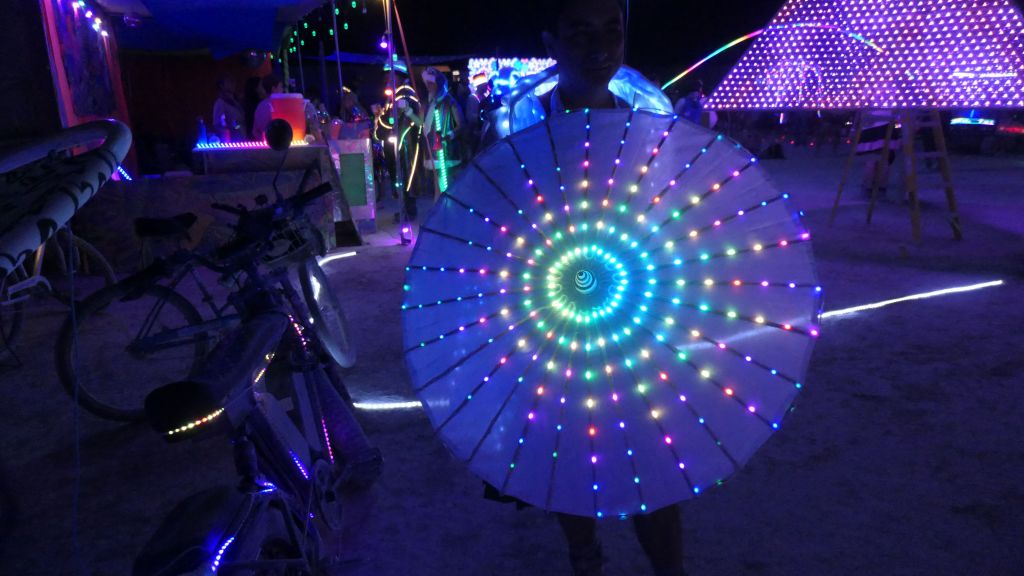
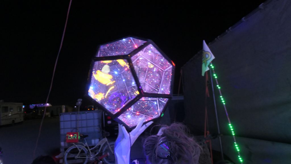
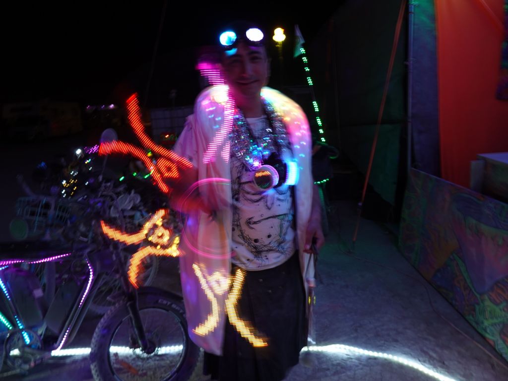
Ran into a bunch of people will cool gear:
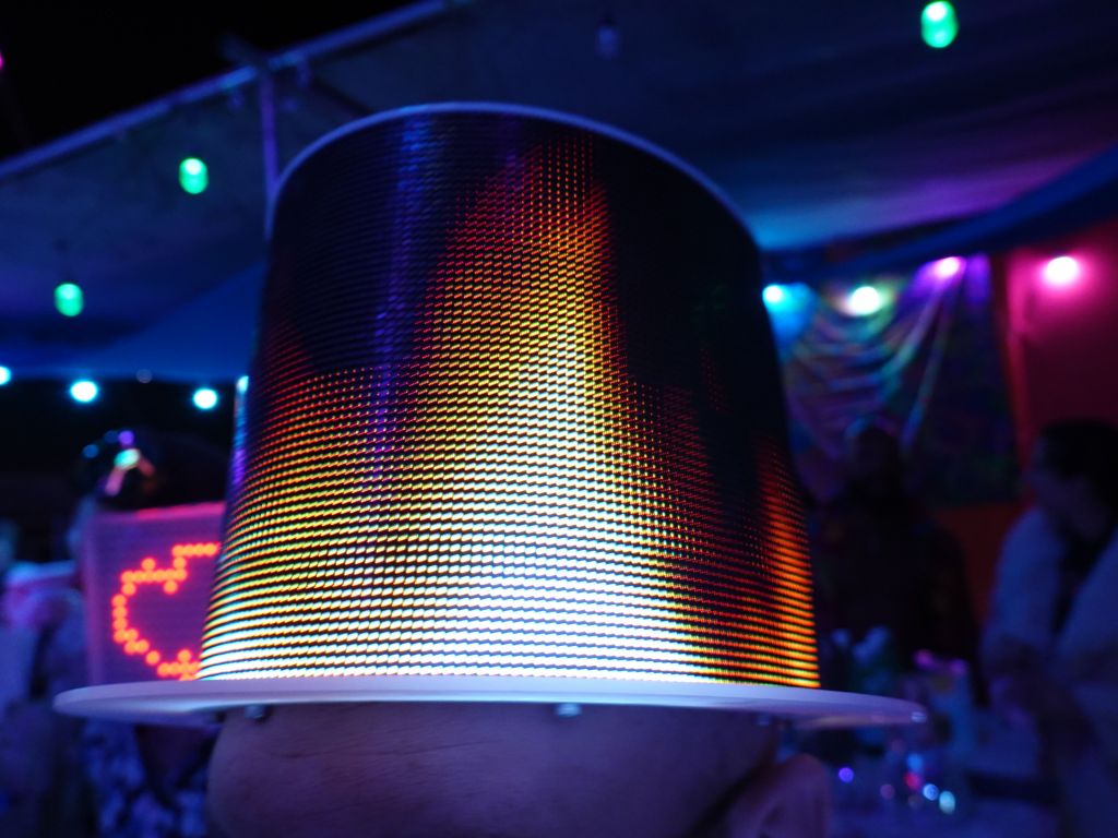
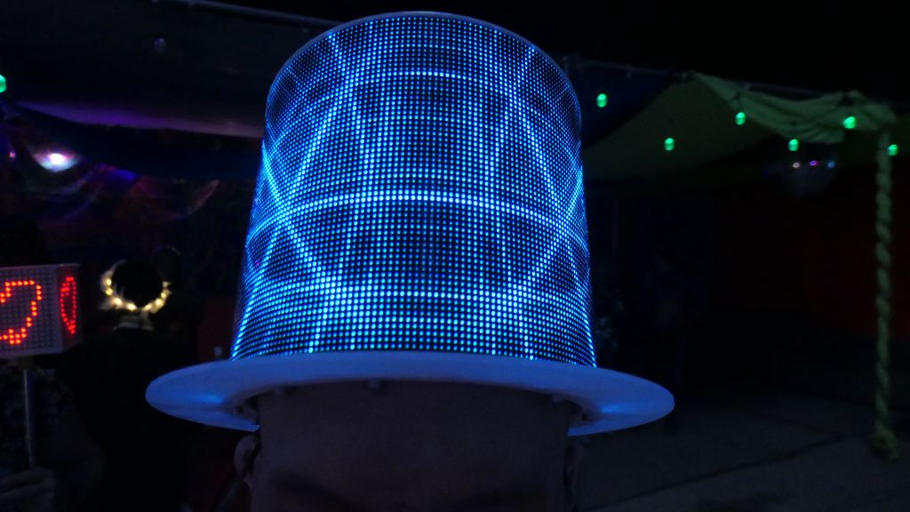
Very cool hat:
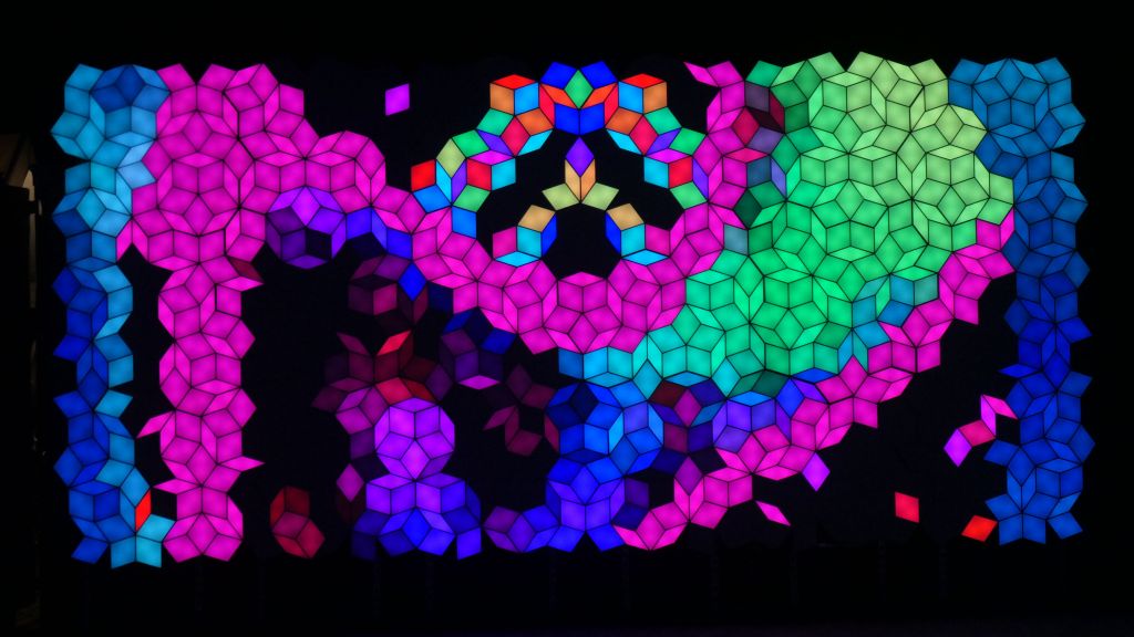
Impressed that the newer panels can bend pretty well
i21*
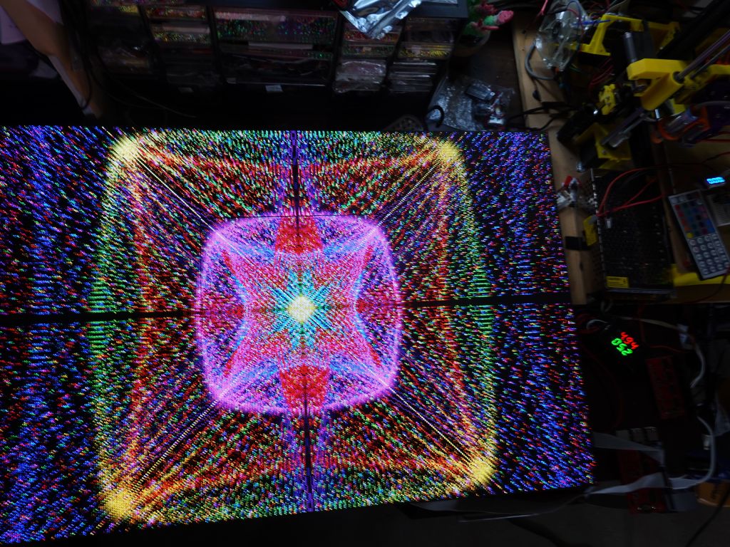
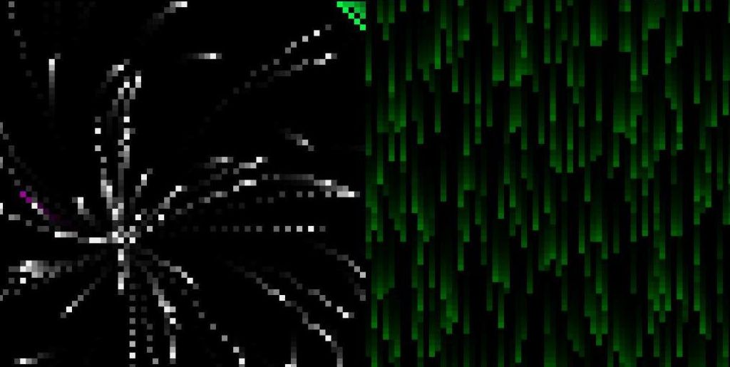
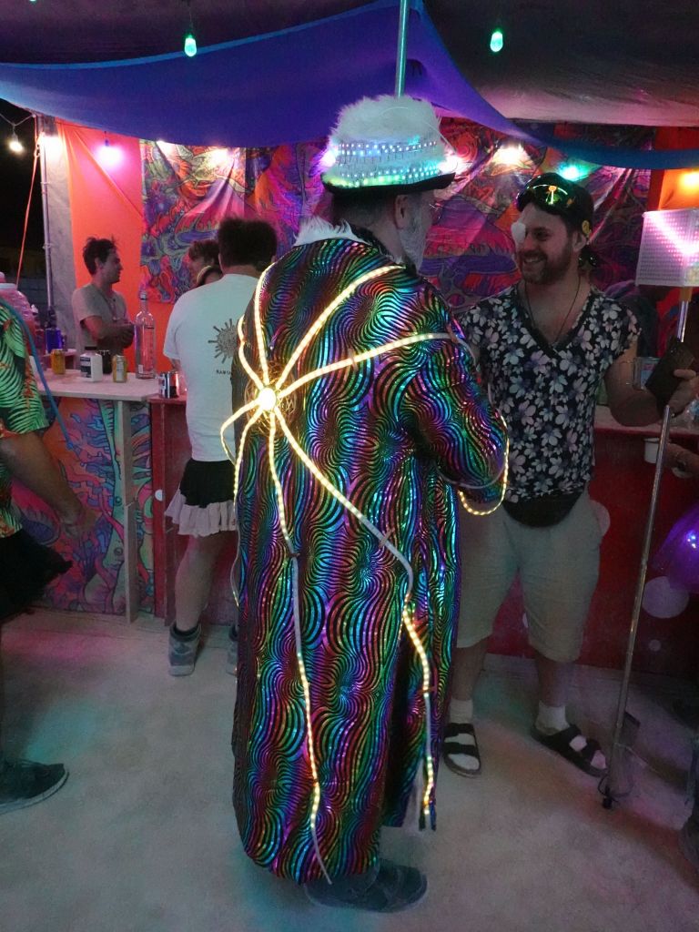
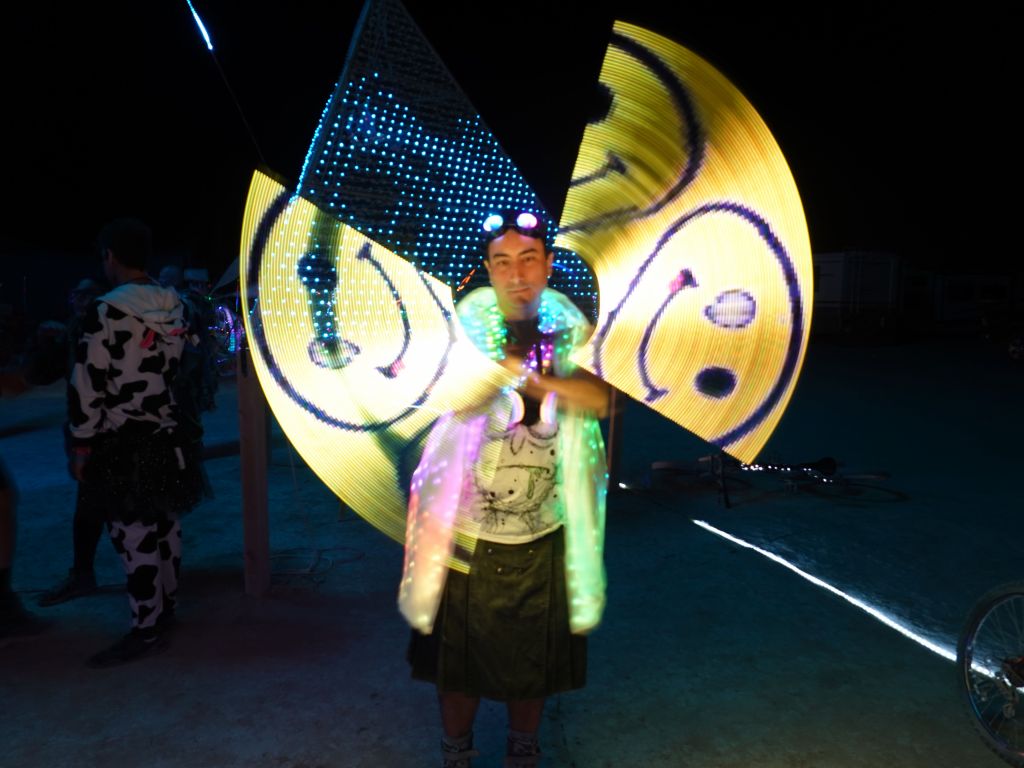
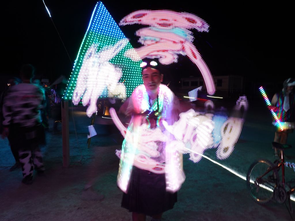
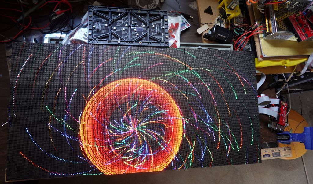
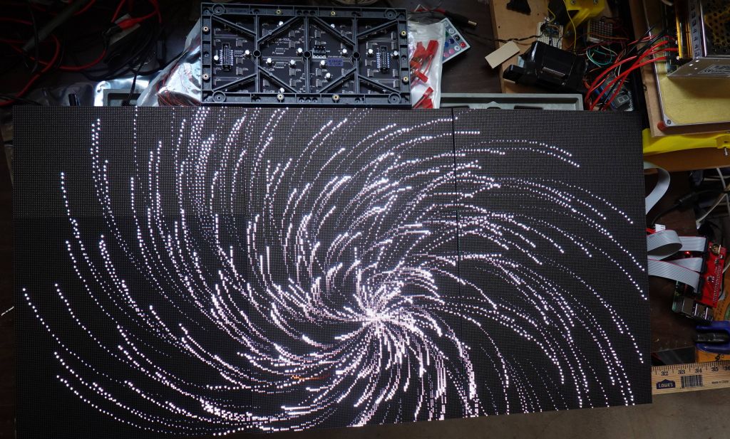
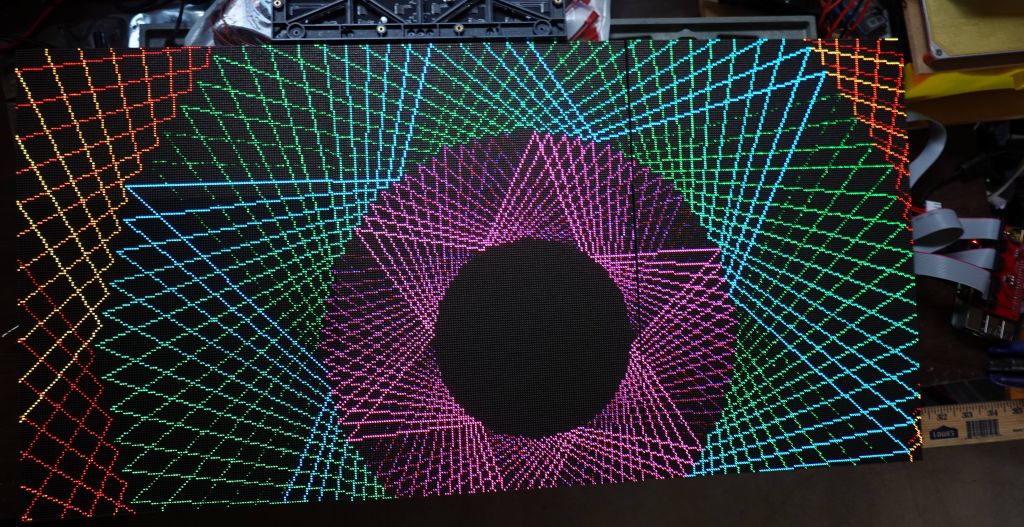
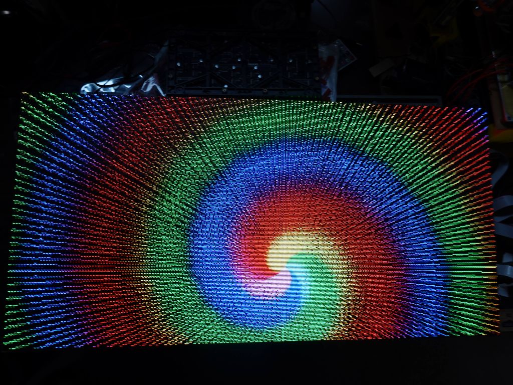
a lot of work went into these patterns
Anthony had a lot of cool gear he built, I was very impressed:
Obligatory group picture:
Thank you to Chuck for organizing this year again, it was lots of fun.
π
2023-06-16 01:01
in Arduino, Clubbing, Electronics
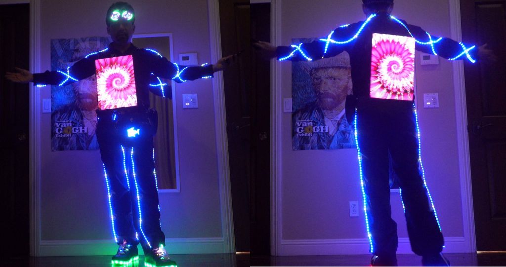
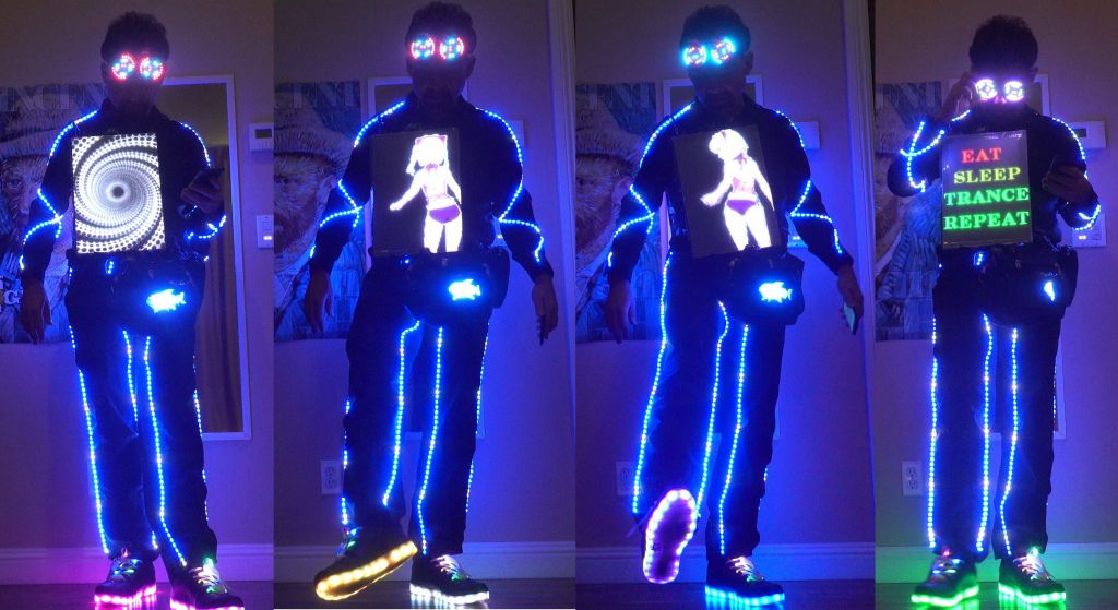
This is the untethered update to my v5 outfit. Please see LED Pants and Shirt v5 on ESP32 and Raspberry Pi with P2 RGBPanels and Wifi for how the entire setup works, and for the new LED strips on arma and legs, you can see Party LED Outfit Version 5.5: Flexible P15 LED Strings, LED Fanny Pack, Rez Inspired LED Goggles, LED Laces and LED Shoes
And if you want even more details and history >>> See this full article on the why and evolution of my LED outfit <<<
For all these years, my outfit has relied on a fanny pack filled with batteries, and with an unslightly tether from the fanny pack to the panels, bringing 2 feeds with 5V (as backup and to spread out the amps over 2 wires). That system worked for many years and would survive the failure of one of the 2 5V connections, or even the 16V connection meant to feed the rPi from its own power source stepped down to 5V on the panels (so that it doesn't see a voltage dip on the remote 5V rail when the display sare fairly bright).
All in all, it worked, but the fanny pack tether and wires were cumbersome, and some security folks didn't like all the wires.
After switching to a new neopixel controller that is directly USB powered, it made more sense to power the panels locally and put the batteries on the panels:
For comparison, the old panel on the left only has the rPi and a small 16B to 5V converter and than relies on that tether cable to the white box on the left which has the DC-DC step down and the ESP32:
finished design with padding, power routing from 3 lipos or 2 USB attery packs
The new version works like the old one, but with batteries directly attached to the panels, which in turn makes them much heavier, but oh well. Video with Lipos and DC-DC converter:
However, the more interesting upside is that I could also replace the 16V lips that get stepped down to 5V, with 5V USB Battery packs. the reason I never did that at the time is that the entire system takes way more than the maybe 2.5A you can get from USB packs on a good day. A somewhat cumbersome workaround to this problem is to use 2 USB battery packs with 2 independent outpus each, meaning 4 independent 5V busses able to put out up to 2.5A depending on the battery pack. So, I split my power system in 4:
front LED panels (3 panels) (1A or more depending on pattern)
rPi (about 1A depnding on CPU load, but must be a nice consistent 5V or the rPi will complain)
Neopixel string run by the ESP32 output if desired. This one might brown out but can be put on a separate USB pack to avoid taking other things down with it
Rear LED panels (also about 1A).
In total it means the whole thing uses about 3A at 5V, or 15W, which means 180Wh for 12h. In theory 2x 99Wh battery packs would work for 10H, but in real life, the first battery pack gets a lot more load since it runs the rPi, so it only really lasts about 7H before I have to replace it. Not ideal, but still nice that I can run from USB instead of lipos if needed:
π
2023-05-17 01:01
in Arduino, Clubbing, Electronics
Version 5 was a bit upgrade with my P2 run rPi run RGB Panels for a resolution of 128x192 per side. The oldest part of the outfit at this point were actually the Neopixel strips I've had for about 5 years, and despite being more reliable WS2813B with backup data line, the PCB traces would break and the chips solder points would eventually break too. The amount of time I've spent fixing and replacing LED strips is more than I'm willing to talk about, but there was just no good alternative, until now.
In the past, flexible LED strands with wires between each pixel did not have enough density, maybe one pixel every 5cm, which was not acceptable for my use. And after many years of waiting, a company finally made P15 flexible strands, one LED every 1.5cm, which looks much better and is even a bit more dense than my previous strips that were P16.6.
Here there are: https://www.aliexpress.us/item/3256804447608449.html . Update, don't buy these, they are shit and broke within hours. See at the bottom
While I was at it, I added a small programmable 16x32 panel to my fanny pack, because why not (the existing fanny packs didn't have sufficient storage, so I ended up decking out mine), and here is the end result:
I have no idea how reliable the strips will be, and unfortunatley they are WS2811 without the backup data path that WS2813 had, but time will tell. I'm bringing it to EDC and we'll see what happens :)
Update: these broke within hours, they were crap.
Version 6.5.1: Ray Wu Strips
Update #1: after the terrible failures of the first strip from the first vendor (the internal wires broke almost instantly), I picked this new one from Ray Wu: https://www.aliexpress.us/item/3256805296356090.html
It ended up being more solid, but the flexing and occasional pulling on the bare strips that were attached with safety pins (I didn't want to glue or sew because it would then be unwashable), eventually caused the strips to fail, although it was more slowly. It worked for 4 festivals in Europe and required some resoldering, but it was not terrible. Still, it wasn't a long term solution either.
Version 6.5.2: Full LED Tubing Protection
So, I tried one more way to do it, this time I put the LED strings inside water tubing of the exact right diameter (fishing them in was a bit tricky), hot glued them on each side, especially the side they are soldered to RC servo connectors which I use for all the electrical wiring.
The next challenge was how to fasten this, and clothes safety pins didn't do the trick, so I used rolls of velcro cut to the right size, and the glue is so good that I was able to glue the velcro strips directly to the fabric. If somehow it won't hold, I'll superglue it.
End result looks like this:
This is now going to burning man, I hope it will hold, especially with lots of biking :)
Azerone was nice enough to send me some returned RGBPanels, including a bunch of P5 ones, so I started making a matrix with them:
And by the time I was almost done, I got 4 more, so that was enough for 192x128 with 12 panels. That happened to be the exact resolution of my LED outfit, although that one was 128x192. For wiring reasons and optimizing refresh speed with 3 parallel channels, I wired the array the wrong way display wise, but the best way hardware-wise:
Thankfully rpi-rgb-panel has a mode to flip, mirror and rotate the output, so it was easy to get back a 128x192 display, and run th exact same code that my outfit. This nicely allowed me to see the same thing between P2 and P5 pixels:
The v4 outfit was 64x96 resolution (3 P4 panels of 64x32), while the new v4 outfit changes to 128x192 (3 P2 panels of 128x64), or 4 times more pixels running in the same exact footprint (my body size, which ideally remains constant :) ).
Because I now have 4x more pixels, and that would have been too much for an ESP32 or teensy (before teensy 4, which could have done it, but it lacks wifi), I had to switch to something with more memory and horsepower, I went with rPi and Henner Zeller's rpi-rgb-panel library, which also supported more panels like mine that had an FM6126 or FM6127 chip that required a special init string.
The other reason for rPi is that to get a high refresh rate and avoid visible refresh bars when taking pictures with cameras, it was better to run the 3 panels on 3 different channels to give them maximum refresh rate (300-400Hz is possible that way), which is supported by that library, using the active-3 board.
So, easy, I just have to port all my code from arduino/ESP32 to rPi/linux, right? Damn, that's actually a lot of work, and I didn't want to do this, so I was able to do something better, I found ArduinoOnPC, and was able to fork and modify it to add Framebuffer::GFX support and added 3 display outputs:
This combined work allows running my arduino code on linux, mostly unmodified, which means it runs on rPi. Then, the FastLED_RPIRGBPanel_GFX glue driver I wrote to make rpi-rgb-panel compatible with FrameBuffer::GFX, allows running all my 2D code, unmodified and have it sent to RGBPanels through the rpi-rgb-panel driver, I'm glad I didn't have to write :)
So, this is what the prototype looked like now 2 years ago:
In the process, I fixed a lot of bugs in all the 2D code I had when I went to a 384x256 panel which obviously overflowed all code that relied on x and y being smaller than 256, and also blew up FastLED code that assumed that there could only ever be 64K pixels :)
While this was a big milestone and proved that my crazy idea running arduino code on rPi using my same 2D library, was possible, there was a lot of work left to do for my outfit, including changing all the code to deal with a much higher resolution, and days (yes days) of work finding close to 200 animated GIFs in the higher resolution, and rescaling them for my non standard 128x192 resolution. Also, all the fonts had to be changed, and a bunch of other stuff, which took months and months of work (all in all over a year):
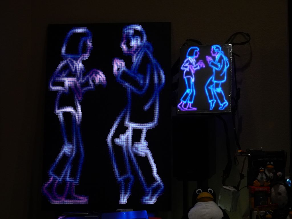
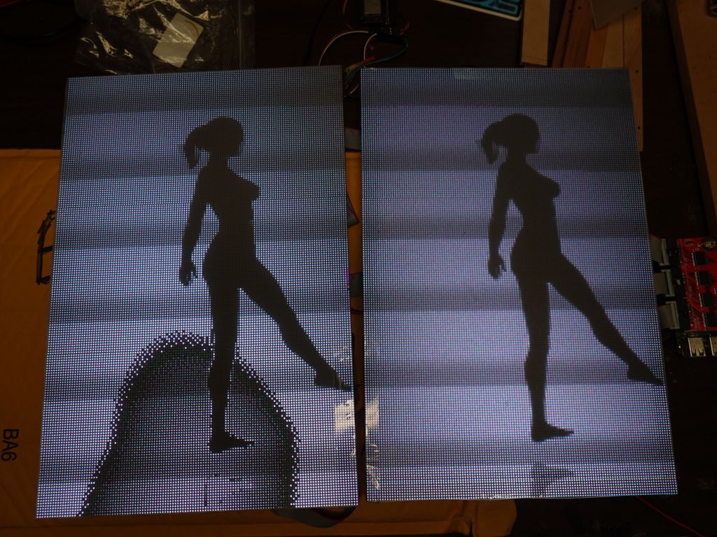
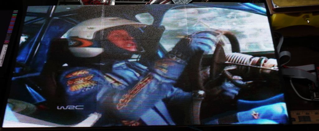
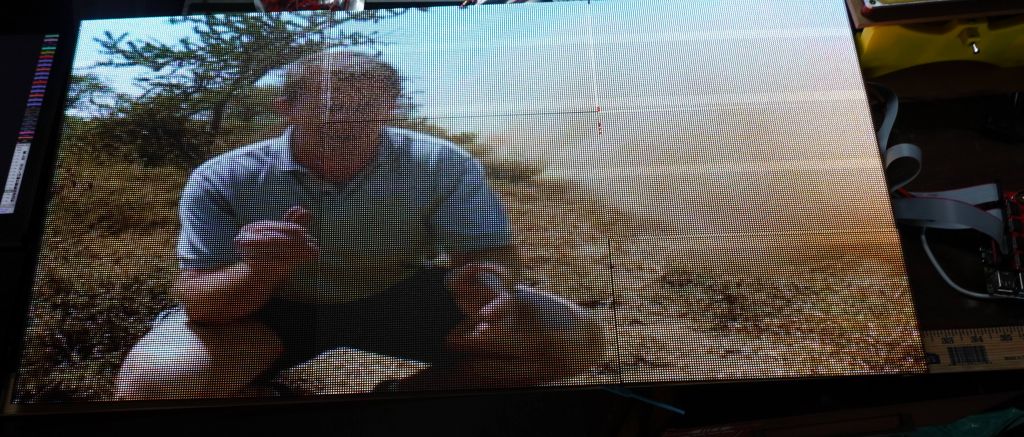
So, this is what it looks like, ESP32 SmartMatrix 64x96, compared to rPi rpi-rgb-panel 128x192, triple channel. Some gifs, I found the exact one in higher resolution:
this gif was so cool, it's only with the higher resolution that I found out it was Pulp Fiction
Other gifs, I found a much better one:
Here is a good video showing the resolution difference between the 2 chips:
Hardware
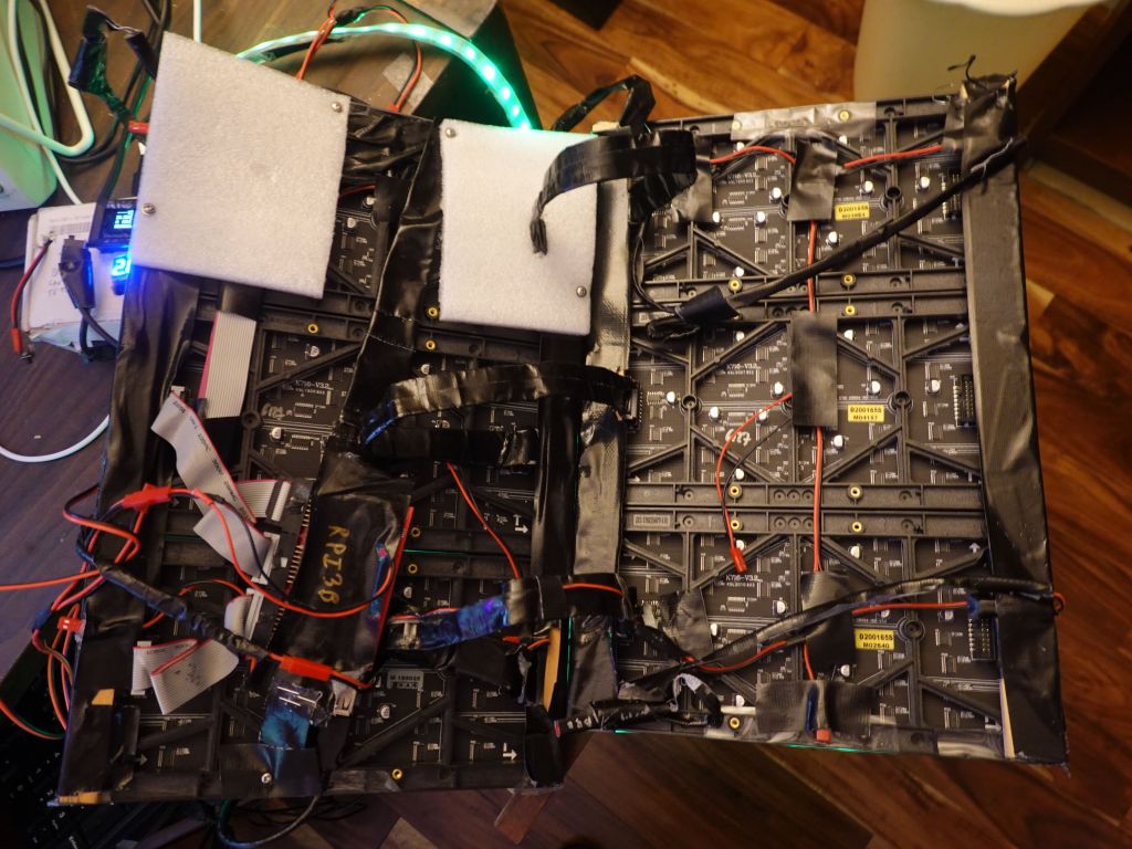
The hardware got a bit more complicated, especially as my wiring wasn't giving reliable enough 5V power to the rPi causing random failures. Eventually I had to feed the battery voltage (16V) via a different cable and step it down to 5V/USB behind the panels to get full power to the rPi (otherwise when the panels drew too much from the main 5V source, it dipped it a bit too much and caused issues).
It does not look great, it's meant to be serviceable and easy to debug, and that part is against my body, so people don't see it :)
For wiring reasons, I had a nice trick with the front panels would shift out bits, and I would send them to the back panels with ribbon cables. If you know how RGBPanels work, it does mean that a BCM plane meant to be displayed for an interval t1 in the front, ends up being displayed for an interval t2, when shifted to the back. Because of random luck of the order of BCM planes, it happened to work well enough with SmartMatrix, so it saved wiring for me (no need to splice the output to go to front and rear panels). Unfortunately with rpi-rgb-panel, the BCM planes are displayed in the opposite order it seems, so the output shifted on the rear panels, is visibly not good:
Unfortunately, there is no good fix to this outside of splicing cables, which I didn't want to do, so instead I slightly hacked the rpi-rgb-panel library to shift output bits twice. This is a bit wasteful for refresh rate, but things were fast enough with 3 channels, that I could afford the software hack and losing half of my refresh speed.
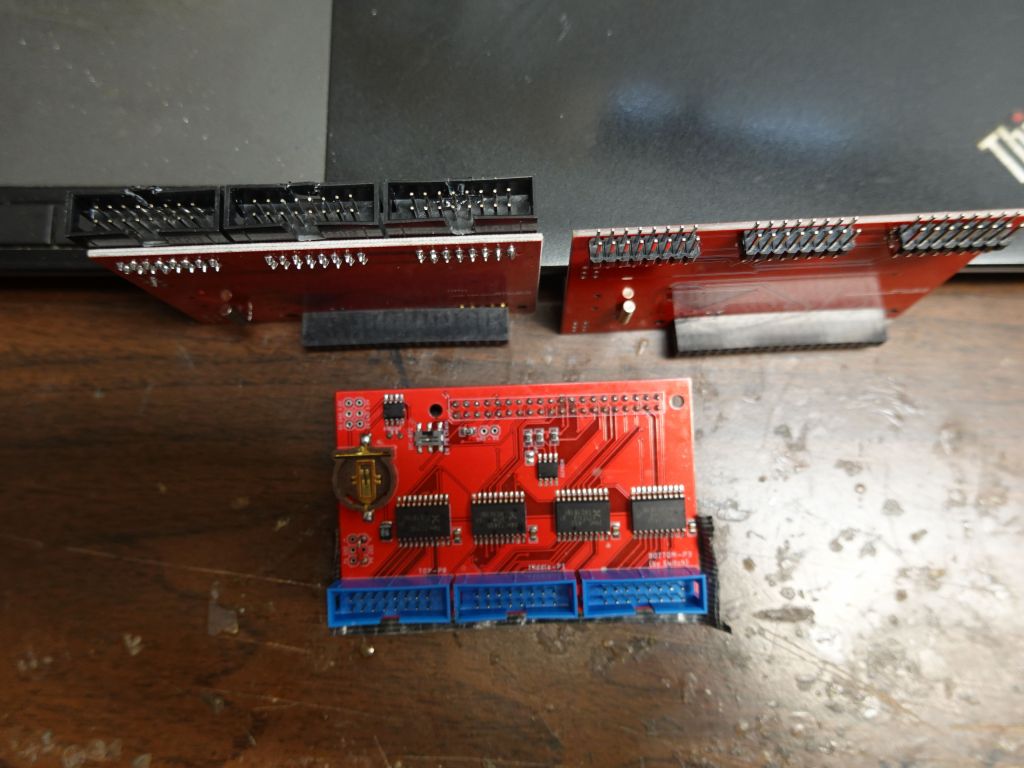
Another issue with the ribbon cables is that the active 3 board is wired to have the cable stick up (i.e. towards my belly). I worked with the nice folks at electrodragon to get bare boards without the connectors soldered and looked at how to best make it work for minimal height footprint. Bottom in blue is the original which sticks up the wrong way, upper right is what I would love to have but isn't possible because the traces on the board would have to be rewired (pin order is wrong when the plug is put underneath), so I had to settle with upper right, some angled connectors and I had to move the key hole from one side to the other for the cable to go in the right way.
I really wish I could have done this, but the wire order would be wrong
Then, I also had to protect the panels with my kitchen cutting board sheets that I've been using. It's not perfect, but they act as diffusers and protect the pixels a bit, because the P2 pixels are so small that they fall off if you look at them wrong:
Battery Use
The new setup uses a bit more battery, first because of the rPi, and also because the new panels use slightly more power, although not 4 times more because the pixels are 4 times slower, so the amount of light is somewhat similar. I had to upgrade my setup to allow adding a 3rd 80Wh battery for longer festivals (12 to 14H with 240Wh). With 2 batteries in the black box, I get about 8-9H.
ESP32 - rPi Integration
Because all my code was written for ESP32, including Wifi code that generated pages on the fly from code, thanks to https://github.com/distrakt/OmEspHelpers , and the ESP32 still runs the neopixels on arms and legs (plus IR input, although it's become a bit obsolete now), I took a very unusual approach of running my code on both CPUs a tthe same time.
The ESP32 runs the demo, and blind outputs it to an RGBPanel that isn't there anymore. At the same time, its debug serial output is connected to rPi which reads it as a text input over a ttyUSB serial port. The rPi code can run in independent mode (where I control it via ssh from my phone, haha), or it detect a hearbeat from the ESP32 over serial, and read commands from the ESP32, including what demo to run. So, the ESP32 controls what demo is run, tells the rPi to switch to that demo and display to the RGBPanels. That makes the rPi a bit more than just a glorified graphics card/GPU since it generates what pixels need to be displayed instead of just being given a pre-computed framebuffer to display.
I had to make the code smart over time so that the rPi can connect and disconnect from the ESP32 and run independently if the connection dies (which it used to when I had power issues that cause the FTDI ttyUSB to fail routinely when running on batteries).
The rPi can also back-control the ESP32, so when I test at home, I ssh into the rPi, and the rPi uses the serial connection to the ESP32 to tell it what to do, or I can use the web server on the ESP32 and tell it what to do directly.
This means the rPi can work on its own without the ESP32 being needed, except for:
- IR input (it's not really necessary, and linux IR code is very different, so it would be a full rewrite)
- Wifi commands (none of Wifi code works on linux and would have to be entirely rewritten)
- FastLED output would not work well on rPi since it's timing dependent, and also there are no IO pins left on mine with 3 channel output
If I were to re-write a lot of code to make wifi work on linux, that would make the rPi independent and not need the ESP32 anymore (except for the neopixel strips), so I just didn't bother. Also I can brag about having a dual CPU system with synchronization between the chips, which was fun to write and debug.
This bit of video shows how the 2 communicate:
Using Linux integration for development
There isn't much to say about this, thanks to my ArduinoOnPC work mentioned earlier in this page, the exact same linux code works on my rPi and my linux laptop, so I can write and debug my code on linux, which is so much faster.
This shows an example of what it looks like:
Wifi and OmEspHelpers
Ah yes, Wifi, that was a fair amount of code, especially on ESP32 where Wifi is more basic and can cause crashes if you get weird conflicts between interrupts, Flash (SPIFFS or FATFS), PSRAM, IRAM, and Wifi. After looking for an easy to use solution, I settled on https://github.com/distrakt/OmEspHelpers because I could generate the HTML pages from code (saving lost time to update the Flash FS each time, which is slow with 16MB, and not having to worry about syncing HTML tags between static HTML pages code).
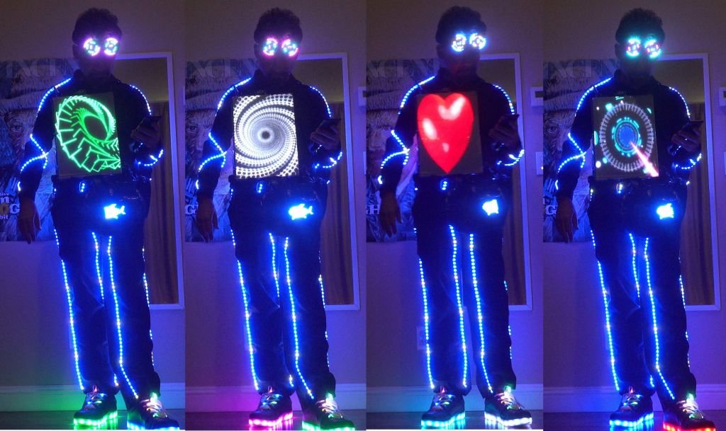
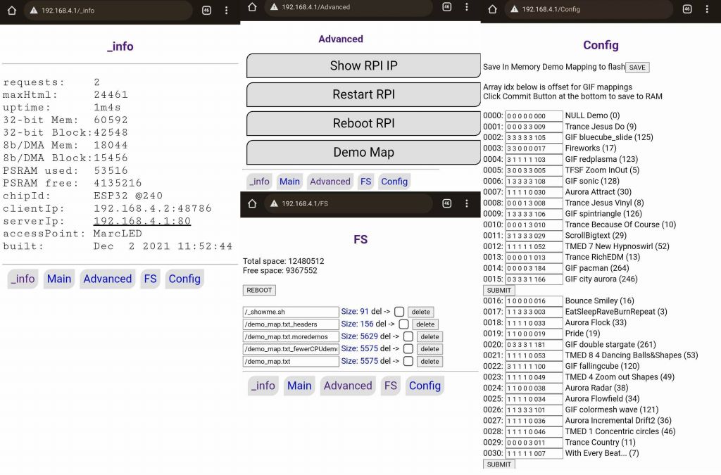
This is the end result, the main screen allows selecting which demos run (neopixel strips + main screen), at which speed, how bright:
there are over 200 2D demos to cycle through, some are machine generated, some are animated gifs
The diagnosis screens give more info on the device, and allow editing the config file that selects which demos run by default depending on the screen size, and whether 'bestof' is selected, or not. The config file also allows choosing the order demos run, in:
Demo of wifi:
Glasses
I got tired of the El Wire glasses, they were unreliable, got dimmer over time, required high voltage (I literally got shocked by that current when wires got frayed), so I got rid of them.
I did try laser cut glass glasses, they look kind of cool, but they are big and impossible to fold.
I ended up getting neopixel glasses which had good battery life, but after I dropped them once, a pixel fell out, and that stopped the rest of the string from working. Thankfully I was able to take a spare neopixel from a strip and replace the missing one. I didn't have the right tools or skill, so I was not able to solder it, but I used glue and that worked too :)
LED Shoes
I've been using LED shoes since 2016. They're fun, but not that reliable: the LED strips keep breaking, if it's not the control module itself on occasion, and of course the battery is too small, which is why I wrote this page on how tohack/improve them, but that also makes them less reliable. I tried to find other options, but have not yet. I had a look at LED laces, and those are not very reliable either (or very bright). I tried to hack these to power from the power supply I added and upgraded in the shoes, but it was probably not the best idea:
I got everything somewhat working in April 2021 for a first show (about 1.5 years from when I started), and then worked through multiple electrical and reliably problems (including serial ttyUSB stability issues, and power issues I had to fix by adding a second higher voltage feed to the rPi). Also fixed sync issues between the chips and other improvements in graphics and menus. I considered V5 mostly done and reliable just in time for ADE 2021, EDC 2021, and Dreamstate 2021
I had the outfit mostly working (with a few occasional hardware issues) in time for Creamfields and untold in Aug-Sept 2021:
This even got me on Romanian national TV :)
I had fun at ADE also, and add time to make custom displays for specific events:
Solarstone looks better than his picture, haha
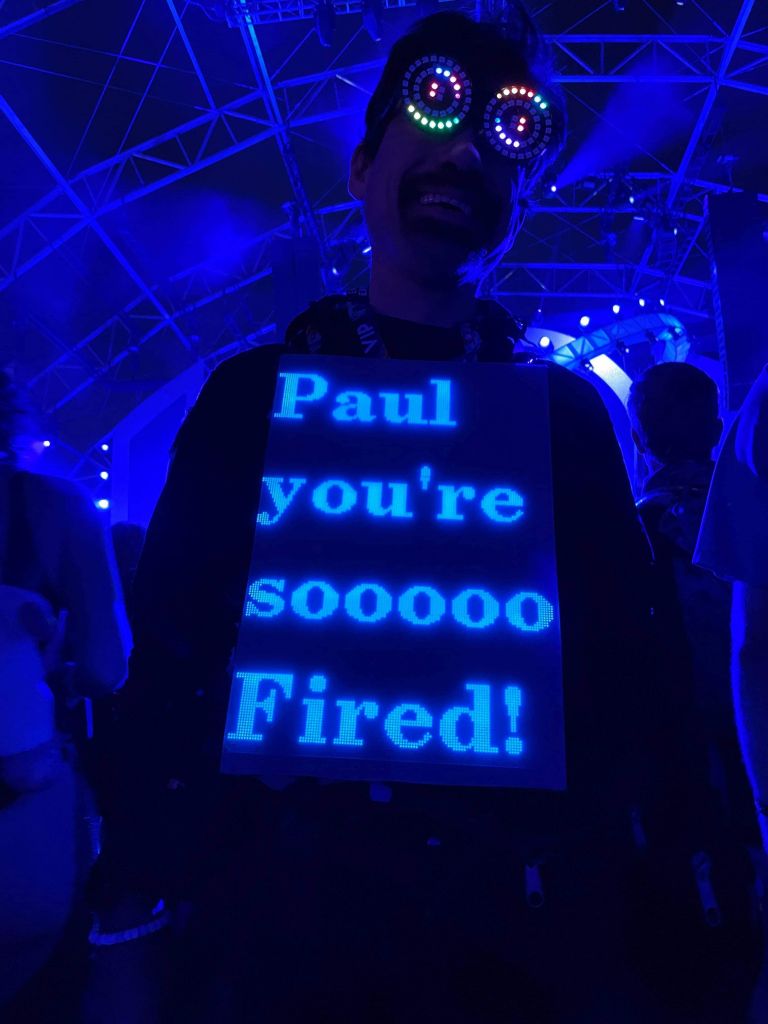
I have some early code that allows me to send text from my phone for special occasions, need to improve the interface:
Future
Higher resolution still? Probably not, I'm happy with this resolution, I can get pictures and text with proper fonts. Besides, that would just get me to the level of strapping a TFT screen to me with HDMI input, which would kind of be cheating and render all my code worthless since basically I'd just be carrying a TV.
I'll add a better interface to send text messasges
Uploading images from the field would be cool
Adding a USB webcam and doing video
Removing the ESP32 and running everything from the rPI would make sense, but I don't feel like rewriting all my web code.
Redoing the power system to work off USB battery packs that could be strapped under the panels (tricky because of amps needed, and would make the whole outfit heavy, because batteries are heavy)
I had already written FastLED_SPITFT::GFX to display Framebuffer::GFX code on TFTs, but that was using the Adafruit drivers that were of varying quality (one didn't support HWSPI on ESP32, so it was very slow).
Later, I found out about Arduino_GFX from Leung CHAN, which is a unified driver for a lot of TFTs of much better quality than the adafruit drivers. There is support for: GC9A01, GC9106, HX8347C, HX8347D, HX8352C, HX8357A, HX8357B, ILI9225, ILI9341, ILI9341, ILI9342, ILI9481, ILI9486, ILI9488, ILI9488, ILI9806, JBT6K71, NT35310, NT35510, NT39125, R61529, SEPS525, SSD1283A, SSD1331, SSD1351, SSD1351, ST7735, ST7735, ST7735, ST7789, ST7789, ST7789, ST7789, ST7789, ST7796
all with a single driver, a single interface, and better speed than Adafruit drivers. Good job Leung, thanks.
Now, why would you use my FastLED_ArduinoGFX::TFT layer, especially when Arduino::GFX has some support for Canvas (equivalent to FrameBuffer?)
First, using a Framebuffer (or canvas) allows for running clear and doing a flush all at once when drawing the next frame is finished
Framebuffer allows you to read back pixels from the framebuffer to shift them or mirror them, or even to dim them (FastLED allows diming the entire framebuffer to give effects that fade old pixels with time)
FastLED and SmartMatrix (or rpi-rgb-panel) all have code that is based on a framebuffer with RGB88 pixels (24bits) which is why Framebuffer::GFX comes in and why I wrote it. All this code works against Framebuffer::GFX and can be displayed on any supported backend.
Support for FastLED and LEDMatrix 2D APIs (which in turn require FastLED CRGB (RGB88) pixel storage, again supported by Framebuffer::GFX but not the Adafruit or Arduino_GFX TFT drivers.
See the Framebuffer::GFX that explains support
So, this is why FastLED_ArduinoGFX::TFT is here. If you want more APIs than just Adafruit::GFX, and you want your code to also work on all other supported backends (FastLED Matrix, SmartMatrix, RGBPanel on rPi, or even running directly on linux to write/debug your arduino code on linux with gdb or ASAN memory sanitizer)
This same LEDMatrix demo now works a lot faster thanks to Arduino_GFX copying data to the TFT faster:
This is 24bpp FastLED/LEDMatrix code running on a 16bpp TFT via Framebuffer::GFX
Basic code example
This basic example is the simplest and skips neomatrix_config.h by defining things "in line", in the code. It's easier to understand, but defeats the main advantage of neomatrix_config.h, which is to have all your definitions outsdie of your code, and allows updating your hardware info in a single file while having all your demo code still work on new hardware by just modifying one common file.
Have a look at this simple file:
https://github.com/marcmerlin/FastLED_ArduinoGFX_TFT/blob/master/examples/MatrixGFXDemo/MatrixGFXDemo.ino
Running Framebuffer::GFX code on a TFT, FastLED_NeoMatrix_SmartMatrix_LEDMatrix_GFX_Demos and neomatrix_config.h
If you have bigger displays like an ILI9341, that's 320*240*24bpp or 230KB for a full 24bpp framebuffer. That fits on a teensy 3.6 or better, but not on an ESP32 where the memory is not contiguous (unless you use PSRAM which neomatrix_config will automatically use for you).
This means that without enough memory, you can define a smaller framebuffer that only covers portion of the TFT, and then render the framebuffer at the desired offset. Check out this example to see how it works: https://github.com/marcmerlin/FastLED_ArduinoGFX_TFT/tree/master/examples/SplitILI934Display
This is the end result, you can see that the ILI9341 is spilt in two, the top half is mapped to a framebuffer, the 2nd part uses direct adafruit::GFX rendering through Arduino_GFX:
tftw/tftw are size of the physical TFT, mw/mh are size of the framebuffer, framebuffer can be smaller than the TFT if there isn't enough RAM to have a framebuffer as big as the TFT, like ILI9341 on ESP32 without PSRAM
gfx_scale is used to keep track of a framebuffer smaller than the TFT (for instance on ESP32 without PSRAM, you can have a half height framebuffer that is then displayed twice, or can be reset with new data and applied to the top of the screen and later the bottom of the screen)
tft_name is simply used to keep track of what TFT name that index is, used for debugging
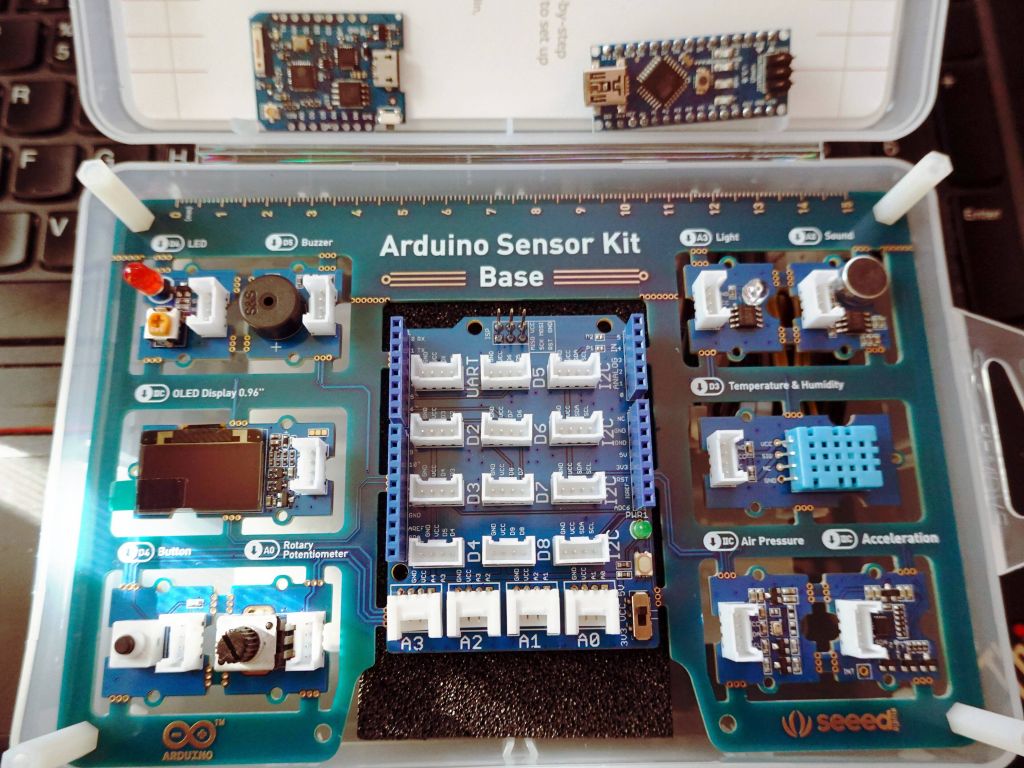
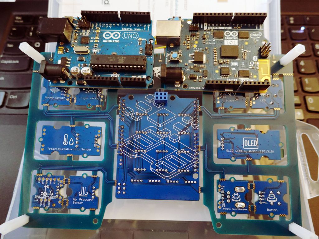
Seeed Studio gave me this sensorkit to review. See the ESP8266 and arduino nano v3 at the top for scale:
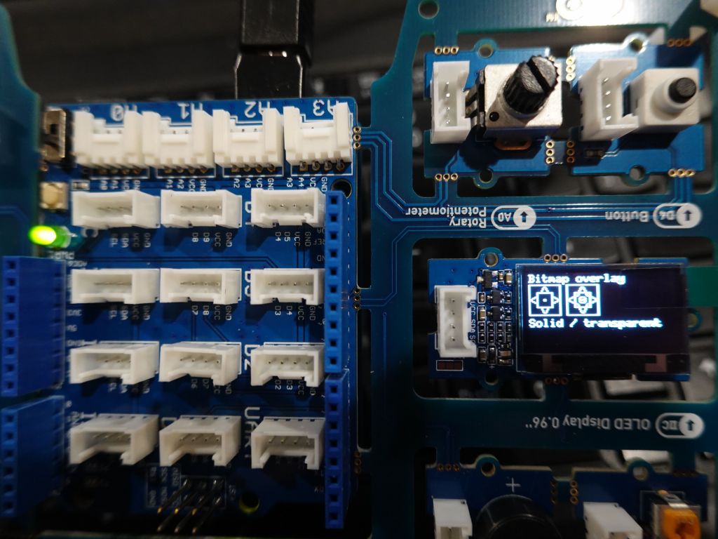
I'll start by saying that the kit is very cool in design: the sensors are wired so that they just work, but they can be disconnected and used with wire cables later:
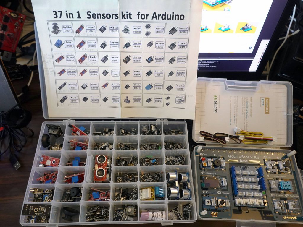
The kit is not as diverse as a previous kit I had, but that previous kit had so many sensors, many hard to use, and came with no instructions whatsoever. The seeed studio kit is much better in that respect and only costs $25:
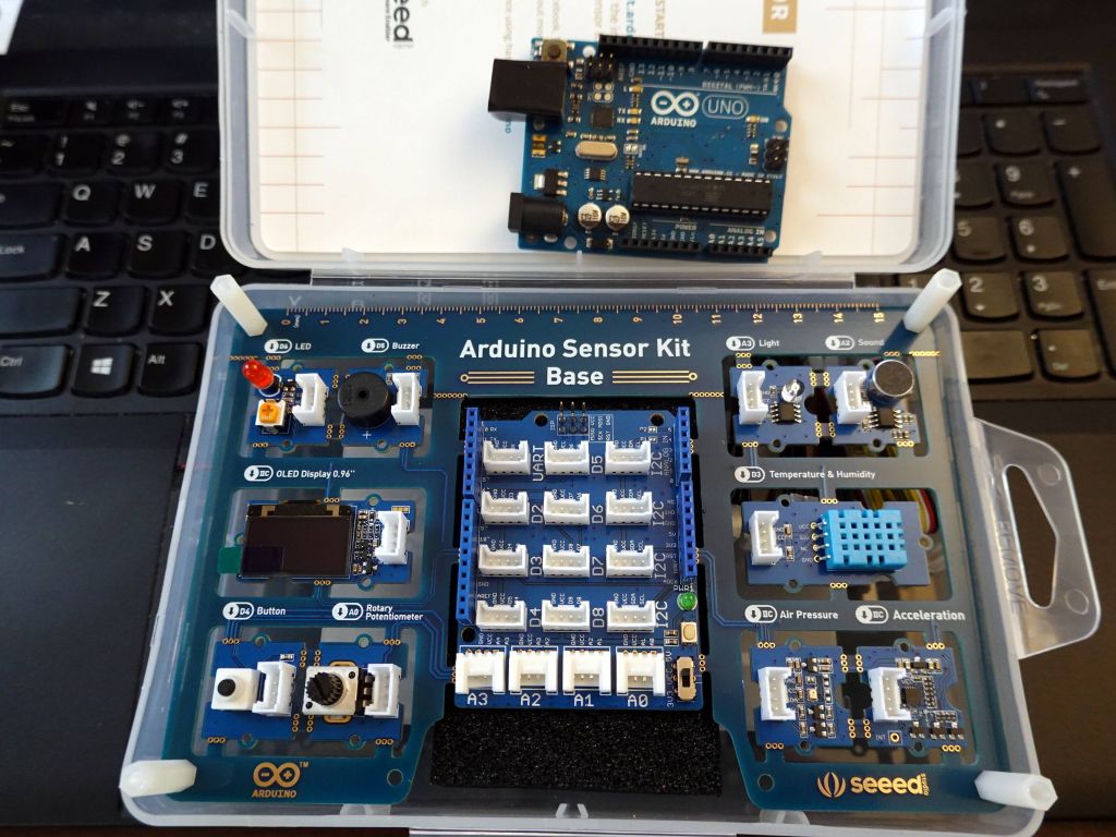
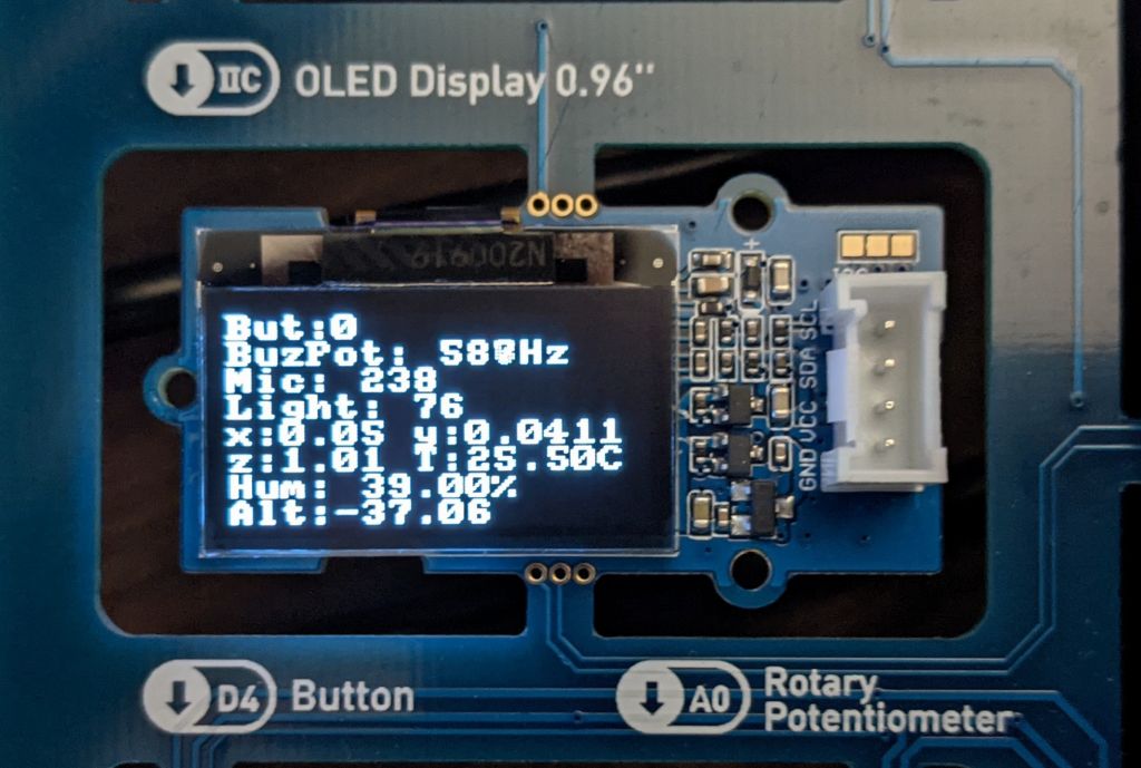
The main downside though was that this was a colaboration with arduino, who thinks it still makes sense to push the entirely obsolete and overpriced arduino uno. The uno is so limited that it's not even funny. The kit could not even make proper use of OLED display due to lack of RAM. I really really wish it was designed to work with a proper 32bit board, like the one shown in this picture (you can also see the wires between the different boards):
After rewriting multiple related libraries, it became confusing to people how they fit together, Adafruit::NeoMatrix, FastLED::NeoMatrix, SmartMatrix::GFX, where does Framebuffer::GFX fit in?
Is Adafruit::GFX still there/needed?
How about LEDMatrix, isn't it a better 2D lib?
What hardware backends are supported?
How the modules/drivers fit together
I made this little graph to summarize everything:
the left shows the hardware drivers supported: FastLED, SmartMatrix, ILI9341, SSD1331, ST7735, rpi-rgb-led-matrix (for ArduinoOnPC on Raspberry Pi), FastLED_SDL (for ArduinoOnPC), and X11/Linux (also ArduinoOnPC)
The 2nd column is the list of drivers I wrote for all those hardware drivers
All those drivers I wrote inherit from FrameBuffer::GFX wihch stores the actual framebuffer in FastLED CRGB 24bpp Format
LEDMatrix is an alternative to GFX that is mostly compatible, but offers its own extensions. I you wish to use it, I modified it so that it doesn't store the CRGB array within itself, but accepts an externally generated one (so that it can be shared with SmartMatrix if this is the ultimate backend, and allocated via malloc and not a global array, which is required on ESP32 for bigger sizes). More on whether you'd want to use it, later.
Low Level Drv|Glue Driver for FrameBuffer::GFX
FastLED     - FastLED_NeoMatrix  -------------\     FastLED CRGB Array
SmartMatrix - SmartMatrix_GFX -----------------\    24bit FB storage        API Support
                                                \   CRGB methods like
AF:ILI9341-\                                     \  scale8/fadeToBlackBy
AF:SSD1331  |--- FastLED_ArduinoGFX_TFT ----------|        |               ,FastLED API
AF:ST7735  /     FastLED_SPITFT_GFX (for AF)      |        |              / (XY 2D to 1D mapping)
ArduinoGFX/  AF:Adafruit (ArduinoGFX is all in 1) |        |

                                                  |        |

ArduinoOnPc-FastLED-GFX-LEDMatrix arduino         - FrameBuffer::GFX------ Adafruit::NeoMatrix +
emulation for linux / Raspberry Pi:               |        |             \ Adafruit::GFX APIs
----------------------------------               /    Adafruit::GFX       \
rpi-rgb-led-matrix - FastLED_RPIRGBPanel_GFX ---/   LEDMatrix (optional)   `LEDMatrix API
ArduinoOnPC X11/linux - FastLED_TFTWrapper_GFX

FastLED_SDL (linux)   -  FastLED_NeoMatrix   -/
Which 2D API: FastLED XY(), Adafruit/FastLED::NeoMatrix, vs LEDMatrix
Old FastLED demos use an XY() function, to access leds[XY(x,y)] to do 2D to 1D mapping. Framebuffer::GFX supports this in a way that you can both read and write while supporting full rotation and tile mapping from NeoMatrix. This is honestly no reason to do this today, you would effectively rewrite the much better XY functionality that's in FastLED::NeoMatrix/Framebuffer::GFX. However, if you have code that uses an XY function, it's fully supported, simply use matrix->XY(x, y) to let NeoMatrix do the real mapping for you without having to worry about writing/rewriting the mapping function for each potential array.
The better and most commonly used API is Adafruit::GFX. Honestly I recommend it because of the sheer number of hardware devices supported by it. It has the downside of only being 16bit color, but if you use it in FrameBuffer::GFX, can you can use 24bit color with it. Its 2nd downside is that on its own, it has no framebuffer, so it is write only. Obviously with Framebuffer::GFX, it does have a framebuffer (which can be a downside on some slower hardware at higher resolutions, see TFT below). To learn more about how to use the GFX API, see https://learn.adafruit.com/adafruit-gfx-graphics-library?view=all
LEDMatrix is a better API with more fancy functions than GFX and native 24bpp color, but it's only meant to work on FastLED, and its matrix tiling support and rotation is pretty non trivial to use compared to NeoMatrix. I would only use it if you need its added functionality. On the plus side, Framebuffer::GFX allows you to run LEDMatrix code on any hardware backend, so you aren't limited there anymore. LEDMatrix pluses are
more primitives, including some flip/mirror screen options
Table_Mark_Estes is just that good, that it's worth having LEDMatrix for
LEDMatrix has Fancy Font Support. In my opinion it's more fancy than most people will need, and Adafruit::GFX built in front support is more than plenty, but it's there if you want it.
LEDSprites is nice if you need sprites, see my LEDSprites-Pacman demo
The SmartMatrix library has its own 2D API, it is quite fancy and includes layers, but it is not supported by FrameBuffer::GFX, so unless you're writing a SmartMatrix only project (which means you won't be able to upgrade to RGBPanels on rPI if you need a higher resolution), I recommend against using it. Technically, someone motivated could make the API work with FrameBuffer::GFX and allow rendering on another backend, but I haven't done that work and don't have the need to do so. If you'd like to contribute that, please do.
The good news is that if you don't know which one to choose Framebuffer::GFX allows you to run all 3 at the same time, thanks to the work done in neomatrix_config.h which while not required, I greatly recommend so that it'll setup everything for you and make it trivial to change from one hardware backend to another one.
If you would like an example of each API, please go to https://github.com/marcmerlin/FastLED_NeoMatrix_SmartMatrix_LEDMatrix_GFX_Demos/ and check the demos in each per API directory.
If you would like to read images from SPIFFS/FATFS (ESP8266/ESP32) or SDcard, see https://github.com/marcmerlin/AnimatedGIFs
This is now the library I recommend for all TFTs instead of the multiple libraries written by Adafruit (supported by FastLED_SPITFT_GFX), not quite with the same interface, and multiple drivers. I definitely recommend https://github.com/moononournation/Arduino_GFX instead for new work.
Arduino_GFX supports running multiple TFTs at the same time if you have different CS pins:
comparison of TFTs
The demos below done on FastLED_SPITFT_GFX look exactly the same with FastLED_ArduinoGFX_TFT except for being faster with this driver.
This is probably the most useful driver I wrote out of all of them, the ability to write your code and debug on linux, without any hardware:
Dealing with pushing bigger framebuffer sizes to TFTs like ILI9341
For long the highest resolution target for arduino chips has been the ILI9341 TFTs. With a resolution of 320x240 over SPI, they push the limits of Framebuffer::GFX a little bit, because it's a lot of pixels to push. Unfortunately, the TFT seems to only support about 14 frames per second for a full refresh, which is needed with the framebuffer approach, and by the time you add required use of PSRAM on ESP32, which is slower than regular RAM but required because ESP32 does not have the required contiguous 224KB of RAM, frame refresh falls down to 8fps. Worse, still, once you add computation of data being sent, demos actually run closer to 5fps.
This is far from ideal, but it's good enough or some uses still, and generally still cool that Framebuffer::GFX can be pushed so far on arduino-like chips. Using RGBPanels does not help there on arduino chips, because there is no arduino like chip that can run such a resolution on RGBPanels (Raspberry Pi can barely do it though, but that's also pushing the limits of the underlying hardware refresh capabilities).
It this ends up being a problem, but you made the decision to stick to the Adafruit::GFX API, you always have the option to remove FrameBuffer::GFX and write directly to the TFT, without having to do full framebuffer refreshes.
If you'd like numbers, I gathered as part of a test between SPI speed, raw TFT speed (empty frame push), loop to push data not from PSRAM, loop to push data from PSRAM. Actual speed in demos is still lower given that it takes time to generate high resolution frames to PSRAM (double PSRAM penalty, one to write, one to read), before they can be pushed.
Arduino::GFX ILI9314
                    tft/gfx/bypass/copy
40fhz, fps no PSRAM: 25/15/22/14       PSRAM: 25/11/21/8
80fhz, fps no PSRAM: 42/19/33/18       PSRAM: 40/14/32/9 (Arduino_HWSPI)
80fhz, fps no PSRAM: 53/21/38/20 Arduino_ESP32SPI
80fhz, fps no PSRAM: 60/20/34/18 Arduino_ESP32SPI_DMA

Adafruit ILI9314 (much slower)
80Mhz: TFT 40fps, NO PSRAM: 32fps, PSRAM show: 12fps

Old Adafruit numbers:
ST7735_128b160: 80Mhz: TFT153fps, NO PSRAM:104fps, PSRAM show: 45fps
ST7735_128b160: 40Mhz: TFT 68fps, NO PSRAM: 56fps, PSRAM show: 32fps
ST7735_128b160: 20Mhz: TFT 53fps, NO PSRAM: 45fps, PSRAM show: 29fps
ST7735_128b128: 40Mhz: TFT117fps, NO PSRAM: 90fps, PSRAM show: 48fps

Arduino::GFX is a lot faster (over 100fps)
SSD1331: SWSPI: TFT  9fps, NO PSRAM:  9fps, PSRAM show:  8fps
Now it's your turn, write your own 2D demos and contribute them back
victory, first time I got those new panels to light up
I ended up getting 15 such panels from the nice folks at Azerone, because they were returns as other people couldn't use them due to lack of FM6126A support in the open source drivers at the time:
if only I had proper mounting hardware, this would be a decent 192x160 array
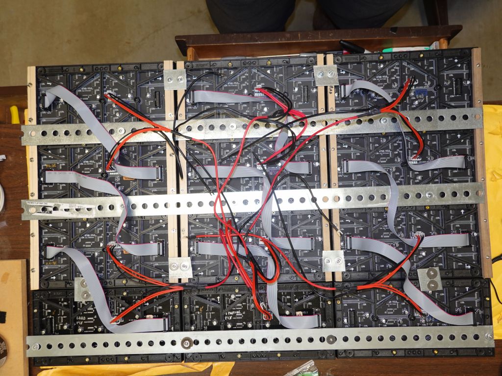
Ok, after writing this blog, I ended up getting a recommendation for rails, which weren't built for this but worked well enough:
you'll need something to cut the rails that are too long. I used a set of bolt cutters I had, some saws may work too, but the rails are pretty thick
holes don't all match, but enough of them do. Note that I put the panels in Z pattern
adding power
on my first try, the metal cut the ribbon cable, so I removed the top loop to avoid having it go towards the metal
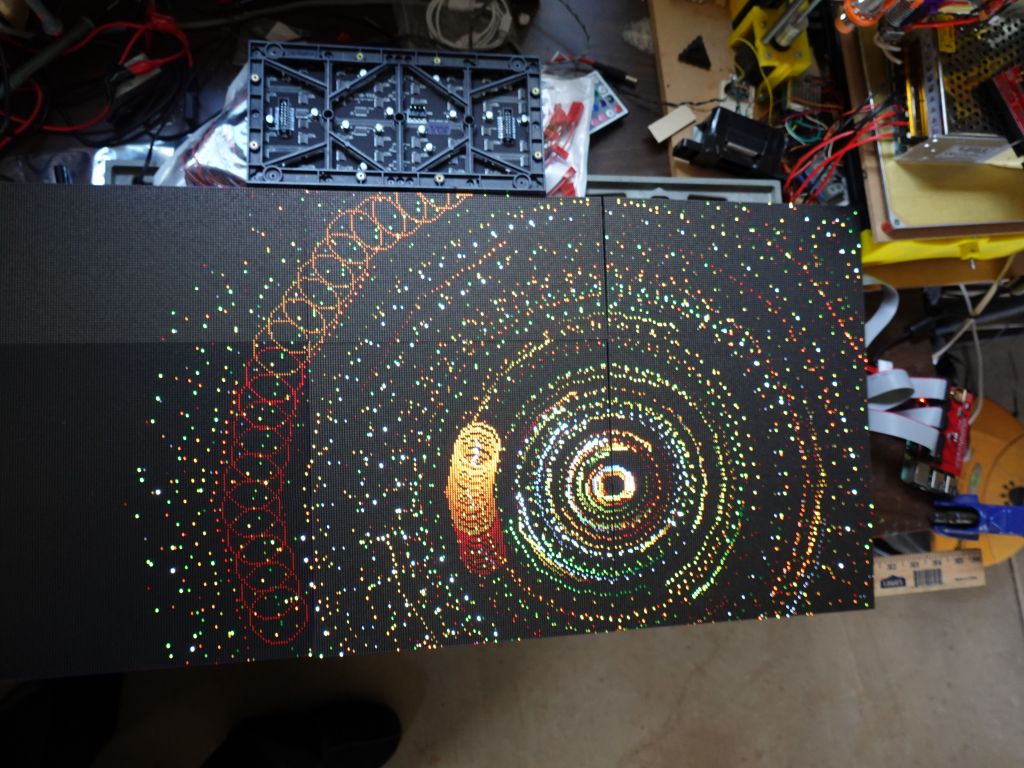
Now, I had an expected problem that hzeller/rpi-rgb-led-matrix did not support panels stacked vertically, never mind if every panel was upside down. I ended up writing a new mapper that allowed both vertical stacking and zig-zag. After that, success was had, end result was about 300Hz for 31K pixels with the active-3 board:
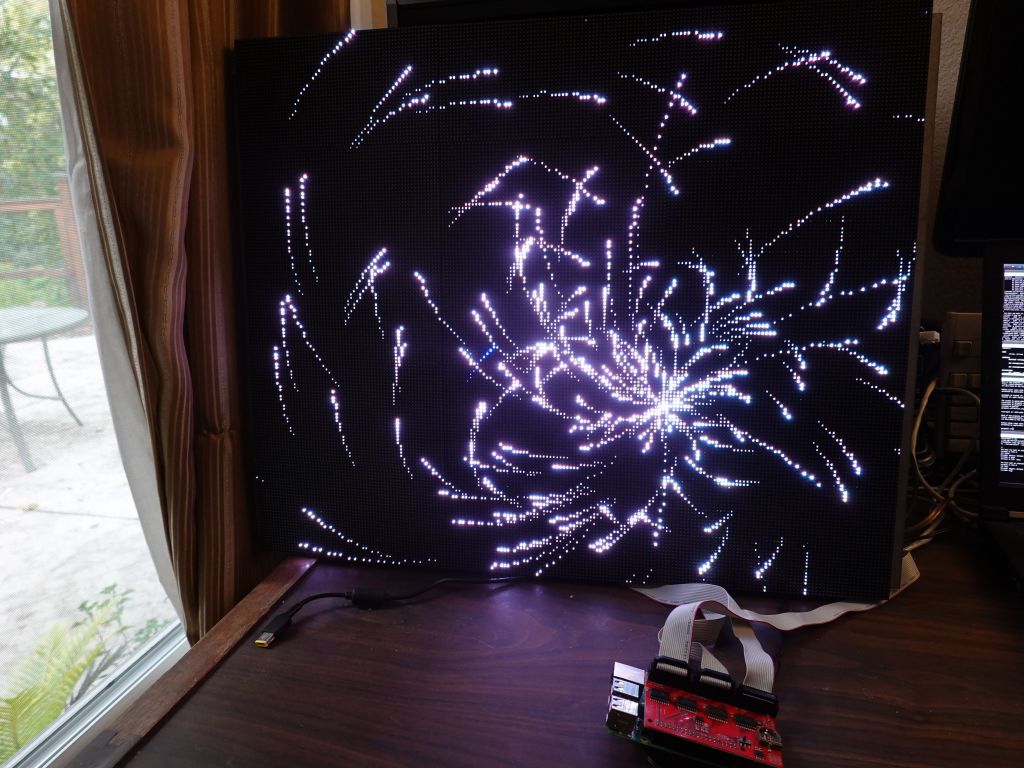
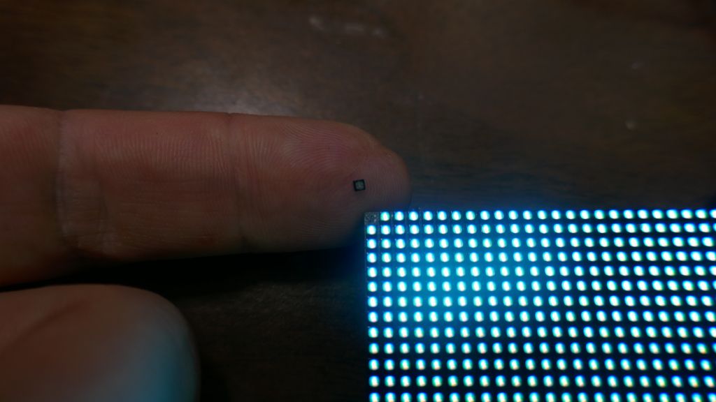
That said, while that bigger matrix with those 15 panels was 192x160, I had bigger plans. I got distracted due to other work, but then P2 panel appeared (2mm per pixel). The downsides of those panels is that the copper traces are so small that pixels come off easily, including during shipping:
even pixels that don't pop off can be partially failed
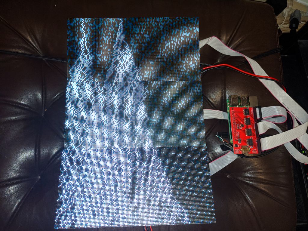
using the active-3 board with 3 chains of one panel each on rPi3
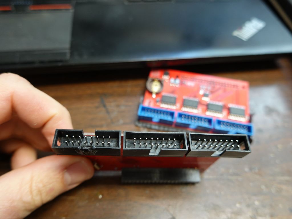
The first issue was that the newer 128x64 panels were FM6126A, which didn't work with default libraries as they need a special init. Thankfully this was added to rpi-rgb-led-matrix. Next issue was that refresh rate was going to suffer, and that's where the rPi solution is great: it allows for 3 channels in parallel thanks to the nice Electrodragon active-3 board.
Chow He from Electrodragon was super nice, and sent me some boards with angled connectors (at my request) so that I could make the whole board more flat for my wearable application. I was really hopeful that I could put the connectors under the board for low profile after cutting the notch and moving it to the other side of the connector:
However, wire routing was such that pins were in the wrong order and it was impossible without re-routing all the wires on the board, so I did the next best thing and put the connector on top of the board, which is still more flush than when it was pointing up:
before (blue), not working (right), and after (left)
bottom is not possible, even after moving the notch
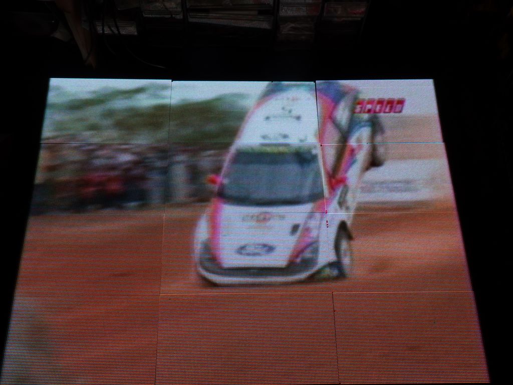
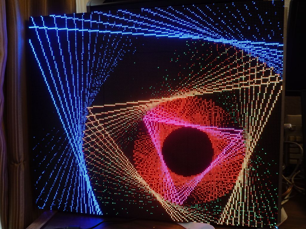
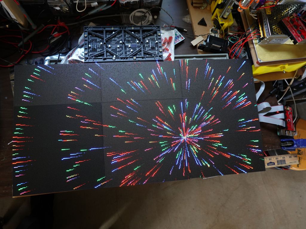
Still, 192x128 is a very nice display that happens to be the same size as my old 96x64 display using P4 panels, but since I ordered spare panels to get around the falling pixel problem, I had enough panels to make a 9x9 array of 384x192. I first tried with with rpi-rgb-panel's video viewer and it worked quite well:
During that time, I did a lot of work on 2D APis for Arduino and lots of backends, and wrote the base class, FrameBuffer::GFX. In a nutshell, it allow talking to a lot of hardware displays, now both on Arduino and Raspberry Pi:
Low Level Drv|Glue Driver for FrameBuffer::GFX
FastLED     - FastLED_NeoMatrix  -------------\     FastLED CRGB Array
SmartMatrix - SmartMatrix_GFX -----------------\    24bit FB storage        API Support
ILI9341 \                                       \   CRGB methods like
SSD1331  |--- FastLED_SPITFT_GFX ----------------\  scale8/fadeToBlackBy   ,FastLED API
ST7735  /                                         |        |              / (XY 2D to 1D mapping)
                                                  |        |

ArduinoOnPc-FastLED-GFX-LEDMatrix arduino         - FrameBuffer::GFX------ Adafruit::NeoMatrix +
emulation for linux / Raspberry Pi:               |        |             \ Adafruit::GFX APIs
----------------------------------               /    Adafruit::GFX       \
rpi-rgb-led-matrix - FastLED_RPIRGBPanel_GFX ---/   LEDMatrix (optional)   `LEDMatrix API
ArduinoOnPC X11/linux - FastLED_TFTWrapper_GFX

FastLED_SDL (linux)   -  FastLED_NeoMatrix   -/
This first demo of simple demo code that scaled up pretty quickly, explaining some of the challenges of scaling past 256 pixels in any dimention and 64K pixels total which hits a FastLED uint16_t limit:
This is an early demo of my shirt code running on a display that is so much bigger than what it was built for:
After some work to find a couple of crash bugs that came from scaling up, I was able to run Mark Estes' fantastic demo code I was able to scale up to such big displays without too much trouble. See Table_Mark_Estes1 and 14.
Table_Mark_Estes:
Table_Mark_Estes14:
Just put back an idea of scale between my first panel at 24x32, all the way up to 384x192. Yes, those are the exact same sprites with LEDSprites:
While 384x192 is starting to push the physical refresh limits that are acceptable for a 3 parallel chain setup, I'm going to try 384x256 for fun once I can get the pixel mapping to be correct. Bigger than that will require multiple control boards and synchronization by some network:
this was my first attempt, panel mapping didn't work, I'd have to write my own
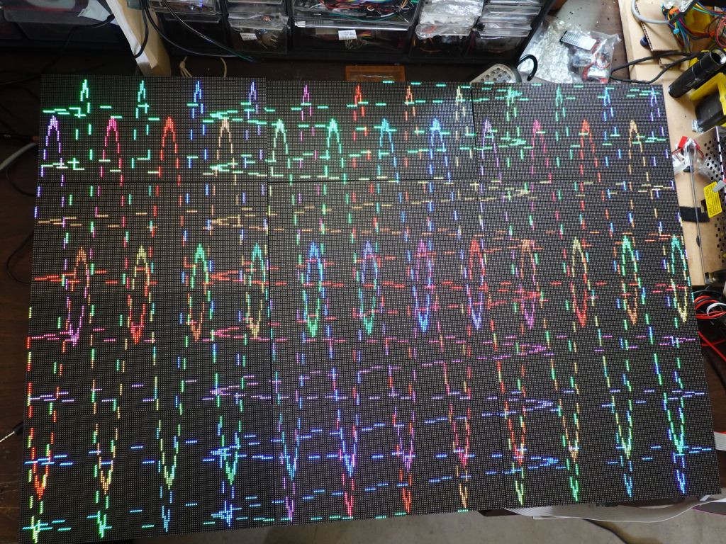
Interestingly, SmartMatrix adds panels in the vertical direction by default, while rpi-rgb-led-matrix adds them horizontally. This means I had to write a new Mapper for it: V-Mapper, which allowed me to make 3 parallel horizontal chains. The end result is not great as refresh rate is only 100Hz, but it works:
success!
that was a lot of work for a low resolution screen :)
video still plays
New pictures of Table_Mark_Estes in the higher resolution:
As above, thanks again to Chow He from Electrodragon for the great and cheap active-3 boards, and big thanks to Hongren Su from Azerone for selling me the panels I have used so far. You can find the Azerone store on amazon for panels you can buy and the 128x64 P2 Panels here.
On the software side, many people to thank, but obviously I wouldn't have gotten started with Adafruit, Louis Beaudoin for SmartMatrix on arduino chips, and Henner Zeller for rpi-rgb-led-matrix of course.
This is a temporary frame I made for my 384x256 array, itself made out of 3 smaller 128x192 arrays I was going to use as portable battery powered frames for my outfit. Unfortunately I used one bolt that was a bit too long and damaged a line on one panel when I screwed it in. Doh :(
Both allow running your basic 2D code written either of Adafruit::GFX, and LEDMatrix, or 2D FastLED on your linux computer:
There is basic serial input/output emulation to allow you to interact with serial debugging on your arduino code when run on linux, and of course you can run the code under gdb.
You can find all the code and installation/usage instructions here: https://github.com/marcmerlin/FastLED_NeoMatrix_SmartMatrix_LEDMatrix_GFX_Demos
This is what it looks like when it's bigger:


")


, not working (right), and after (left)")

")


")