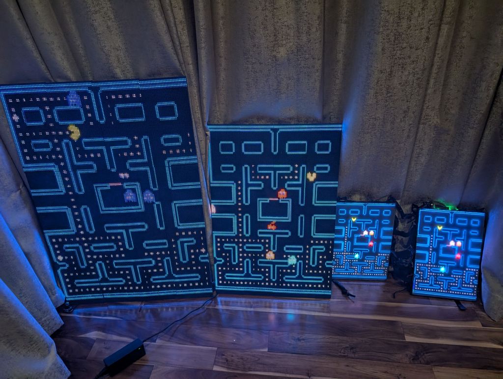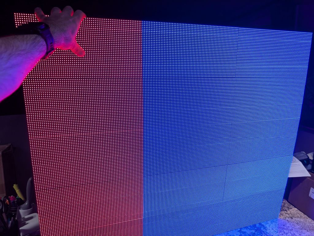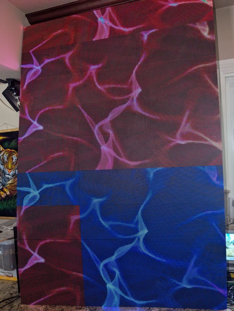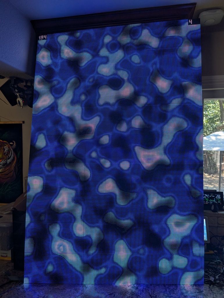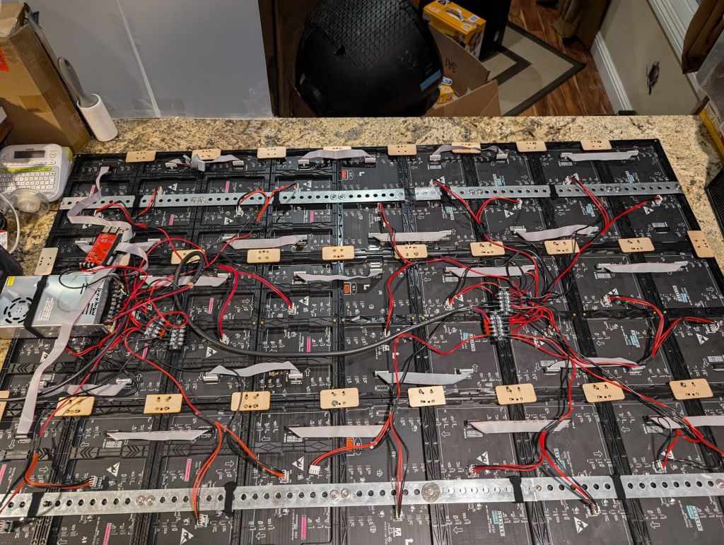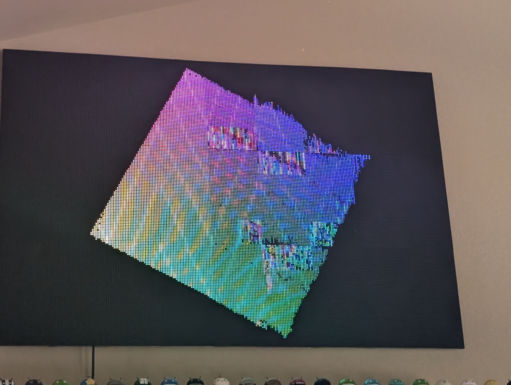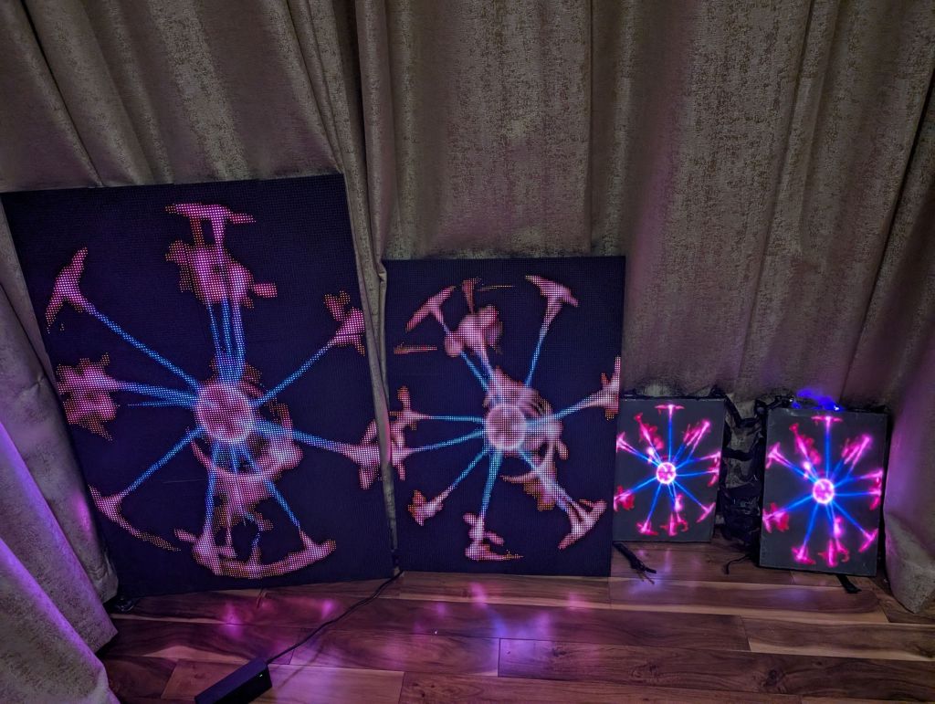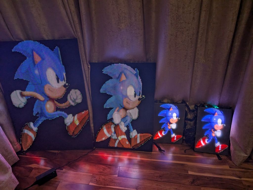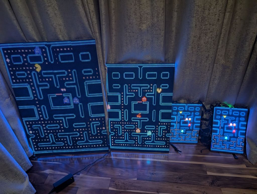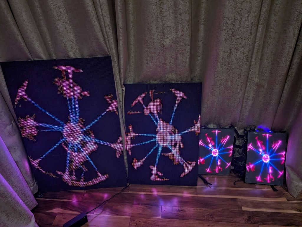
This is what I started with, 128x192 in P2, P4, and P5 panels
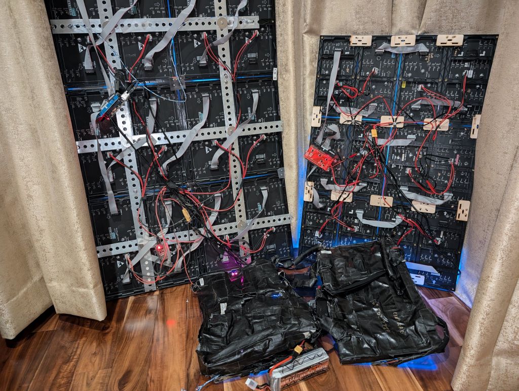
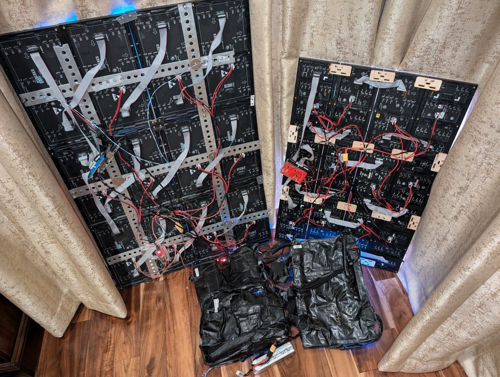
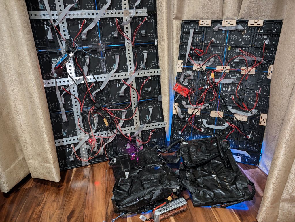
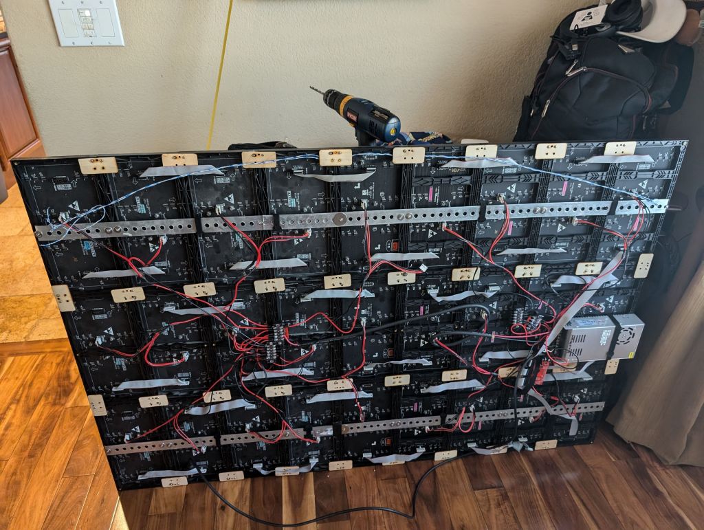
Now let's look at the back and my old (left) vs new mounting method (right). On the left is my "up to then" McGuyver's method of attaching things: using some metal rails with holes, I was somewhat able to aligh enough holes to put some screws in, which kind of held everything together, but not securely:
On the right, a new way to put things together thanks to Marc Estes who laser cut connecting pieces so that each panel could be more securely and correctly attached to the one next to it. Also, note each panel being upside down from the previous one to allow for short ribbon cables and less signal loss, clock drift and crosstalk
Here is the end result of the new panels I put together, the code to reverse panel directions worked:
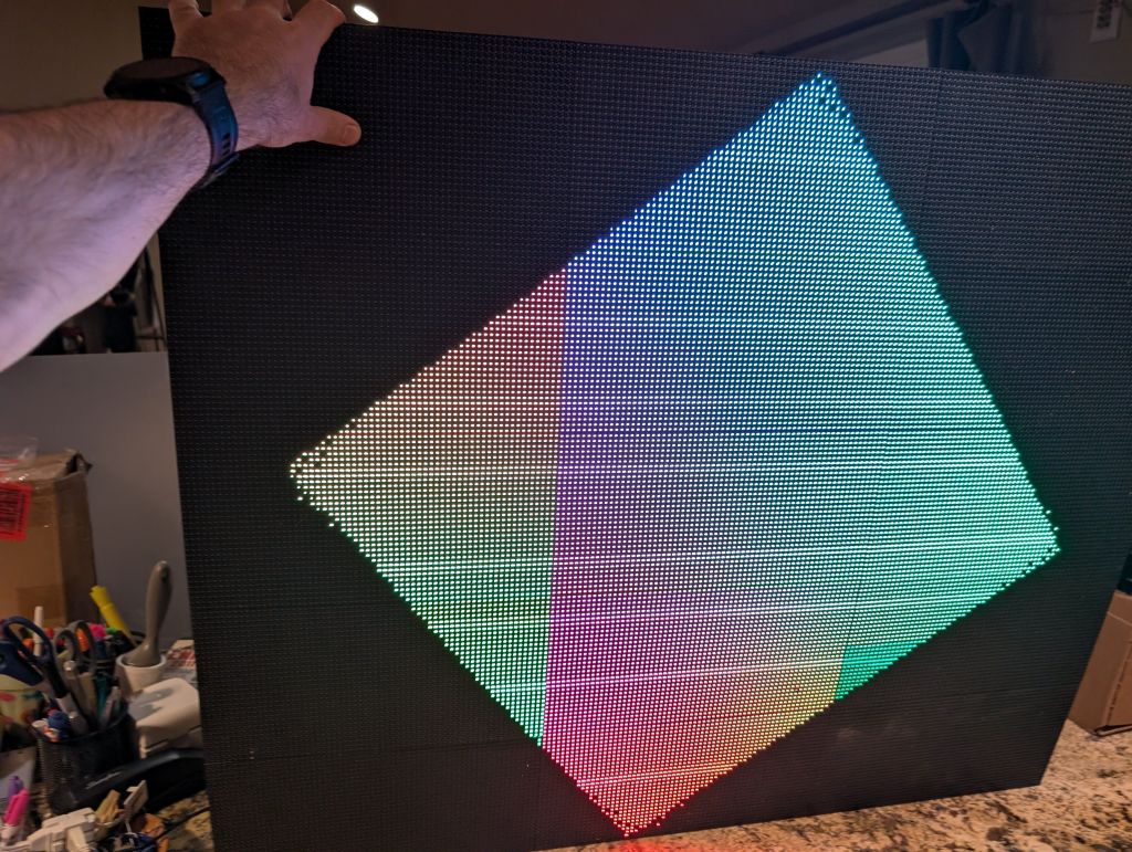
but the colors were broken, see below
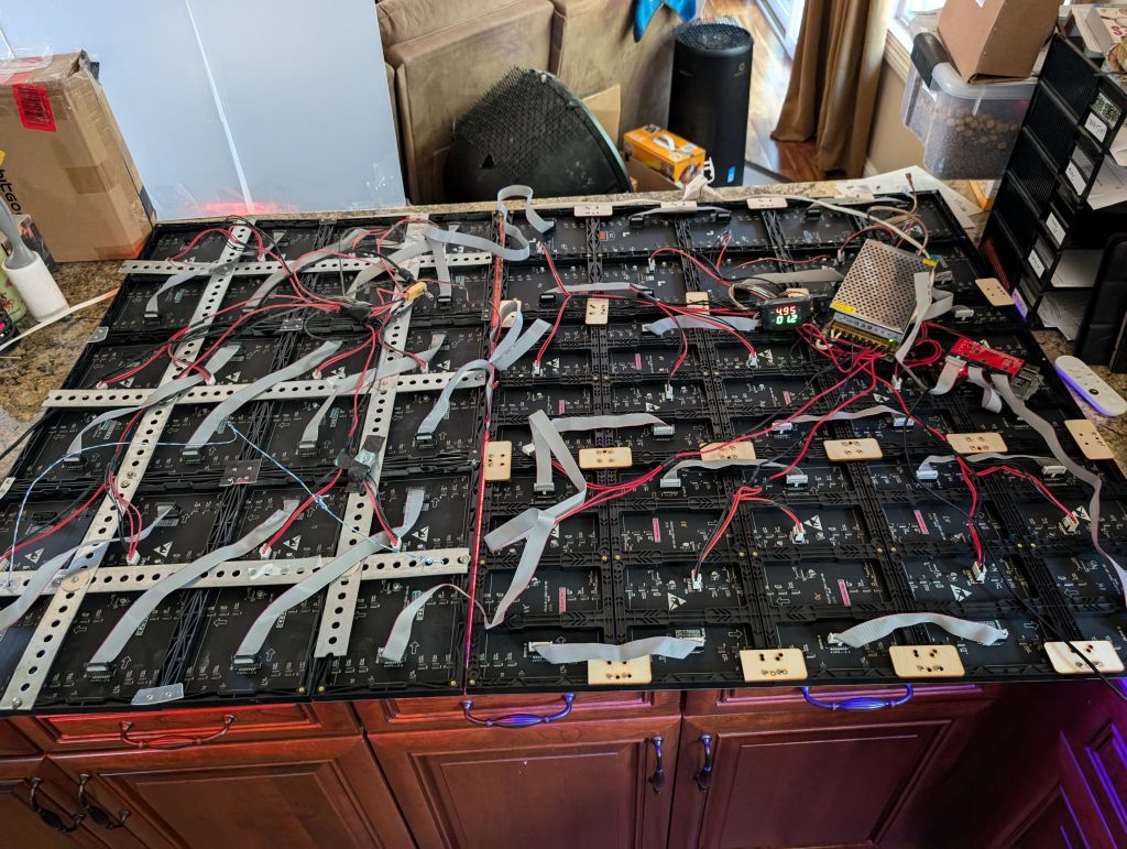
So here is my old 3x4 P5 array next to the new 3x5 array I was building, just testing signal would work:
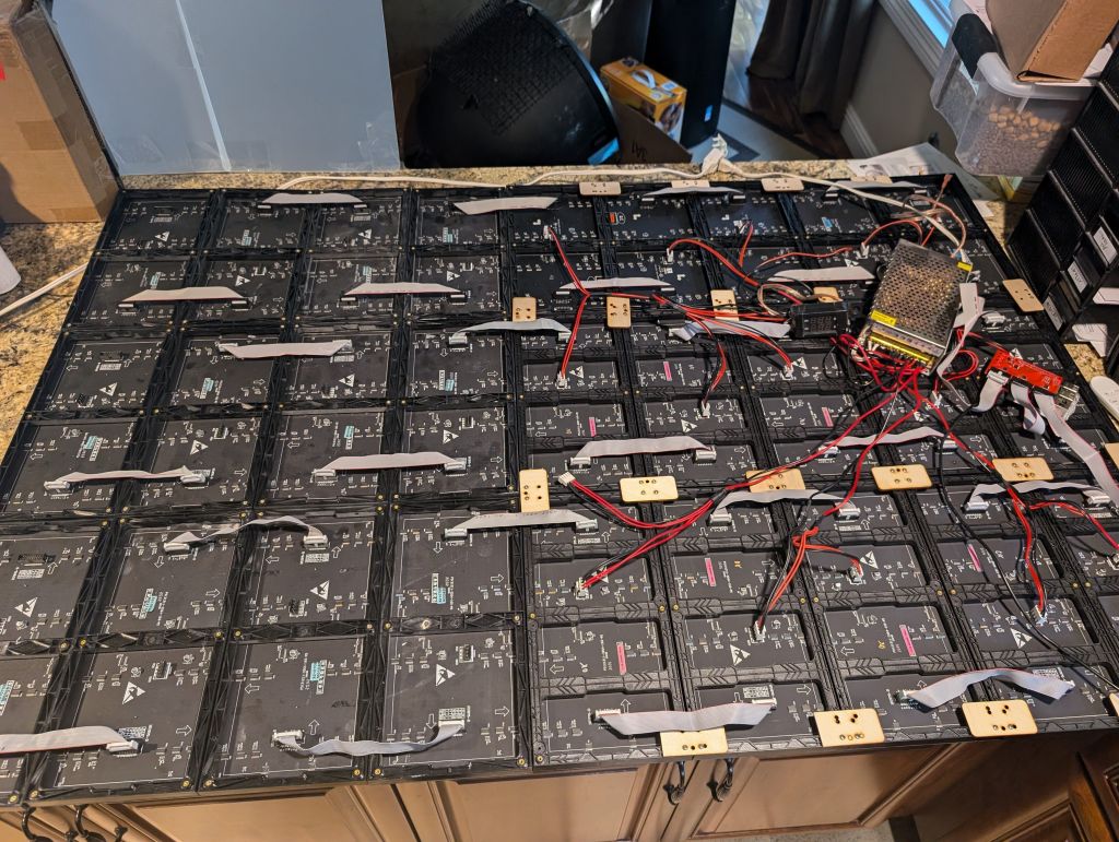
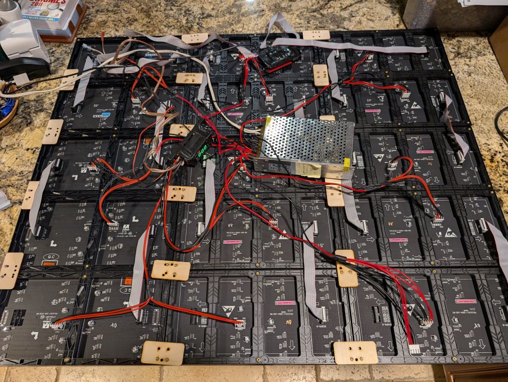
then rewired everything nicely to be the same orientation
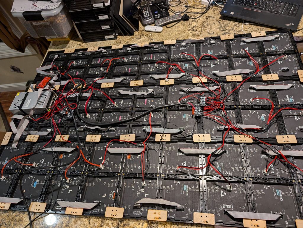
took a while to add power and all the connector bits that Mark Estes made for me
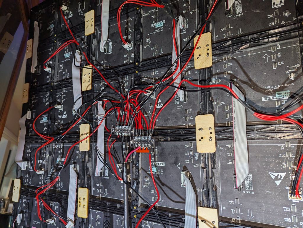
I found those nice power concentrators from amazon
Here are 2 videos that explain the build:
But the colors were wrong. Why? Well, turns out some of the panels were badly wired from the factory and had reversed colors:
So it was all nice and good, until I turned it on:
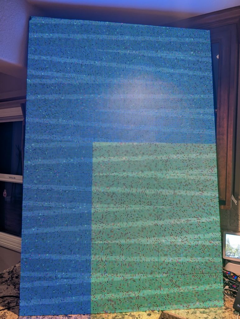
oh great, some of the panels have broken color order
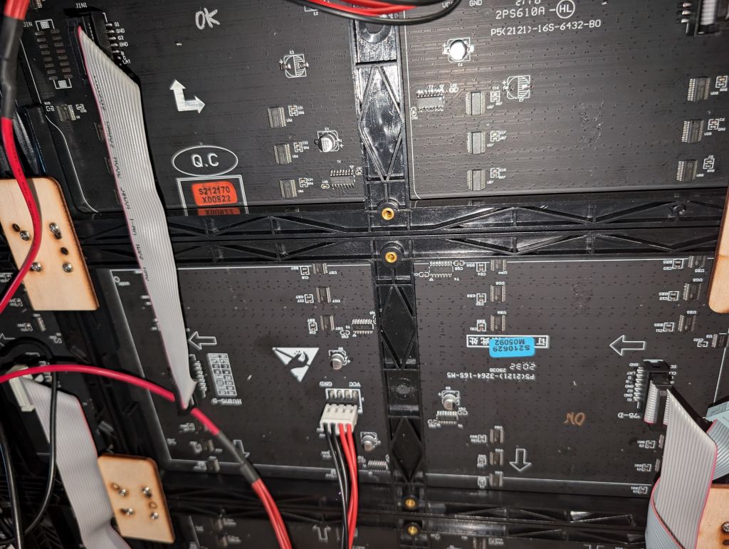
yeah, that's because I got those panels for free as returns, and they are different generations, some with broken colors. I used the orange and blue labels to tell them apart.
Ok, so since I had a couple of damaged panels and I wanted a nice row of matching panels so that the color intensities would simliar enough, I bought 3 more panels. They came with the orange label, so I wired the orange together, and got this:
Son of a.... The 3 new orange label panels lower left, have fixed colors, so they are not the same as the older orange label panels....
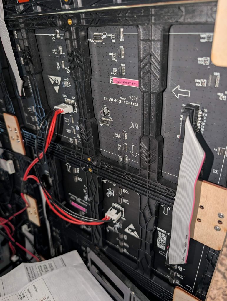
they looked similar enough but they were not
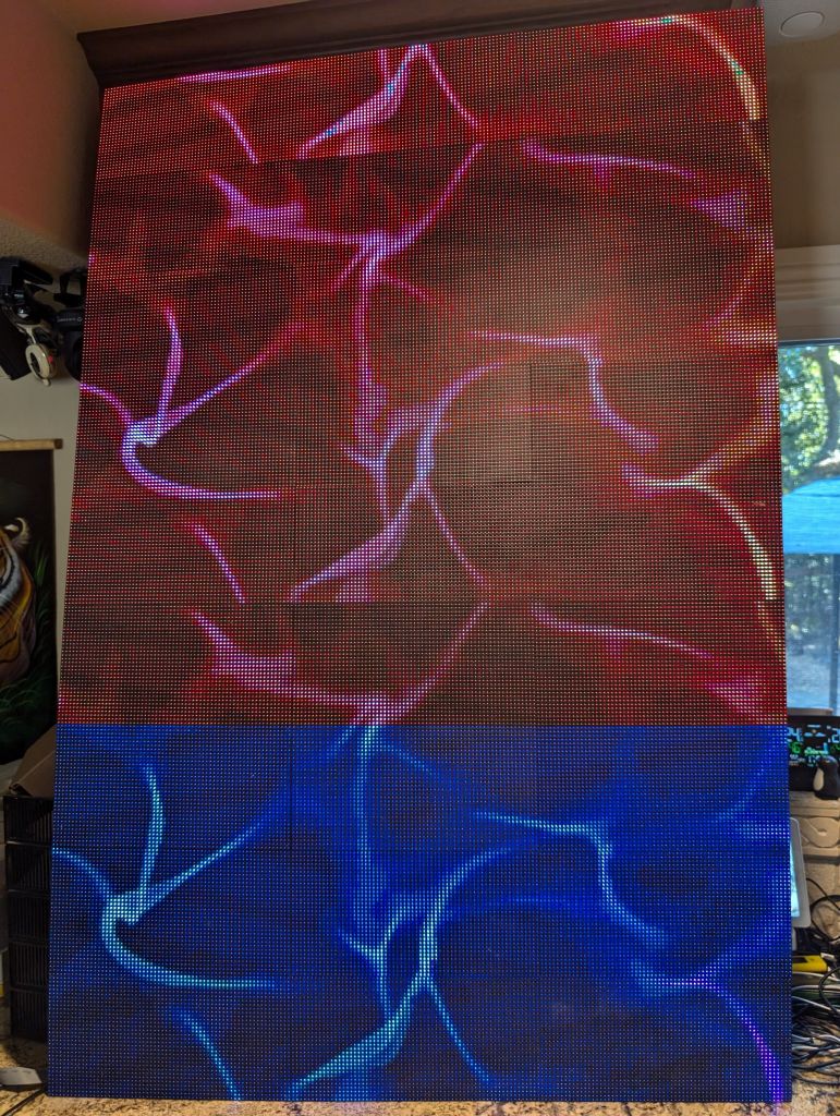
after getting what was going on, I re=wired everything a 3rd time to get bad color panels together
I briefly considered fixing this by swapping the color channels in the ribbon cables but then I figured out it would be less work to fix it in software. rpi-rgb-panel allows for swapping colors on a per panel basis, but not on a per panel basis. Thankfully the code was written well enough to allow very easy remapping of colors per pixel and of course per panel. I also fixed a prior patch of mine that had an unfortunate behavior with Zmapper:v that swapped the order around every time you added a row of panels. Here are the 2 patches:
And after these fixes, finally the panels are oriented the correct way and the colors are fixed:
After more days than planned, it was finally time to mount it on my wall, and that was not trivial, partially because I didn't put enough time into getting proper mounting hardware. I did have some leftover rails I used for added structural integrity, but found out under the wait and stress, they would bend too:
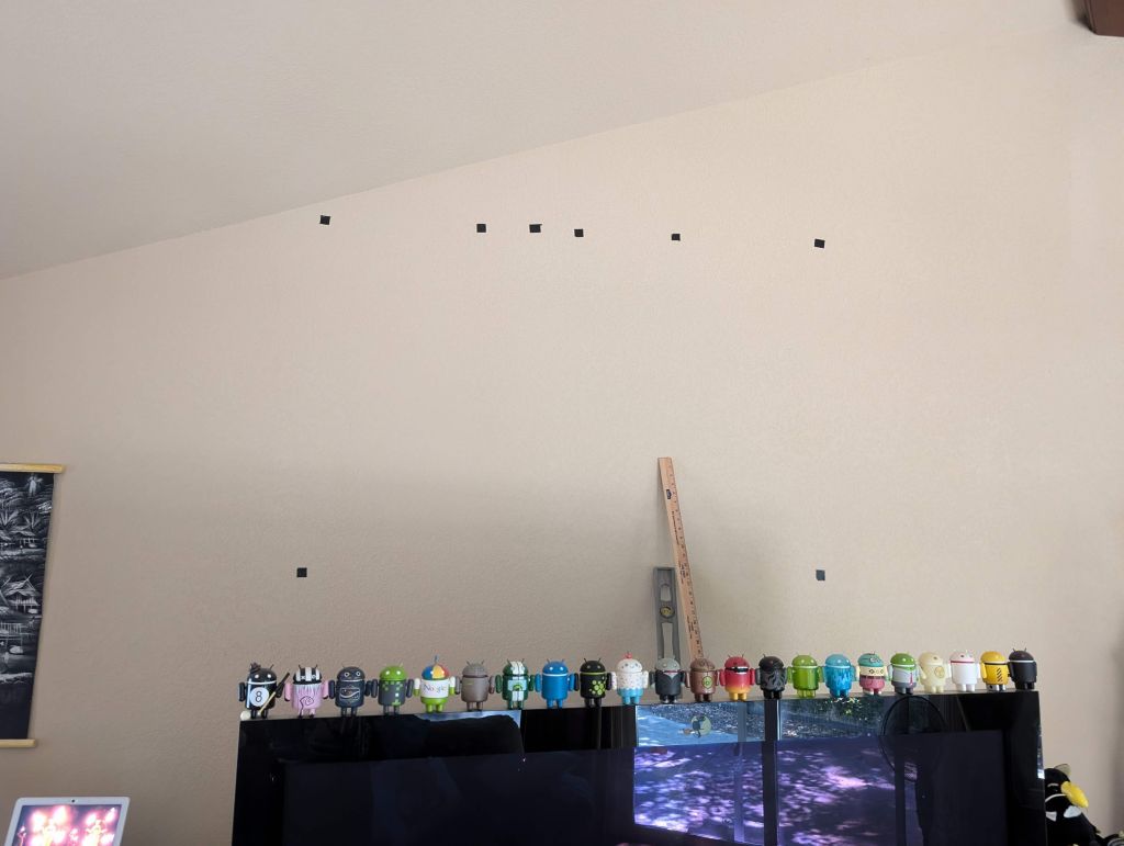
the mounting location was also challenging, made measurements and marks
I used electrical wire as the best hanging wire I had around and put 4 layers just to be sure. Also I found out I had to attach it to the frame in the middle to stop the frame from bending under weight
getting all the attach points under the wire, was totally not trival, but done!
The last thing I had was the native display orientation was portrait, so I wanted to switch to landscape. Turns out rPi3 is too slow to handle an array that big, the data exceeded some internal CPU cache and became very slow, and even more so if I tried the driver's 90 dgree rotate function. So, I tried an rPi4 instead, which showed other interesting electronic bits: the panels on the left are newer and can handle faster update speed while the ones on the right are slower refreshes. This is why it looked like this below. I had to add some delay fasctor in the rPi4 output and then everything was well. Fix was the expected --led-slowdown-gpio=4
See also this page that discusses the cache overflow issues on rPi3, switching to rPi4, and how led-slowdown-gpio can be a bit counter intuitive:
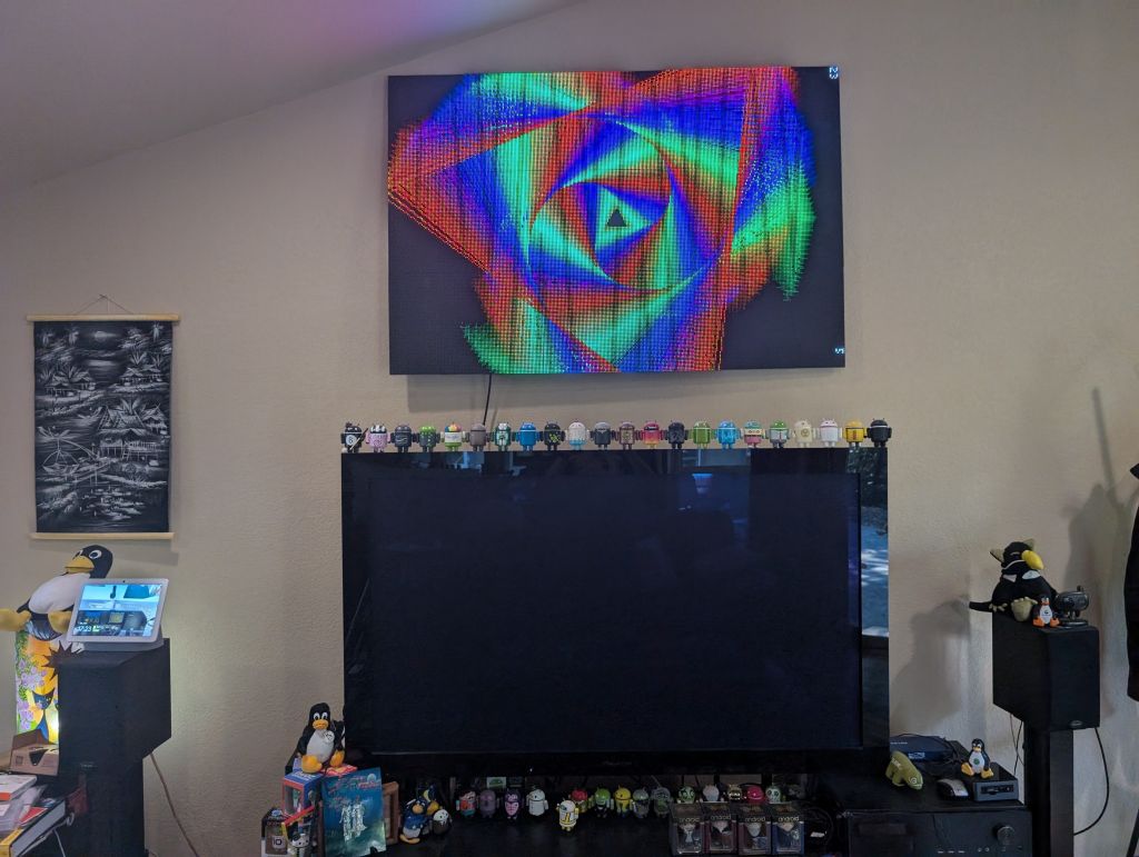
And here is the end result:
