Lithium Batteries have a voltage between 3V and 4.1V, but recently they have been turned into the 1.5V form factor with some electronics that step them down to 1.5V and custom chargers that know how to recharge them via a special protocol, or for the EBL batteries, they have a micro USB plug onboard.
They are of course not all the same real usable capacity, and I've learned not to trust vendor capacity claims anymore either, due to the amount of sellers that plain lie on amazon. The good news is that Neither Xtar nor EBL lied about their cell capacity as long as you understand that the actual energy you can output will be lower due to conversion losses and some safety buffer to give the cell longer longevity.
https://docs.google.com/document/d/1z9o7O5o70SxJnQwKHJD8JdlPdScZZ1o09scHqUlDxeE/edit?usp=sharing
Here is a quick summary without pictures:
New Xtar: Rating: 4.15Wh, Charge: 5.5Wh, 3.45Wh Usable discharge at 1A
This is the only lithium battery that drops its voltage to 1.1V to give you a low voltage warning. Other batteries I tested just die with no warning. That alone is a reason to select it. I tested it with my garmin GPS and it gave me 2H of low battery warning before finally dying. Very nice!
It is also the battery that gave me the most actual discharge capacity
Seller is not lying about cell capacity (thank you) which of course is higher than actual usable energy due to conversion losses
New charger is unfortunately bigger than the old one and drops the USB-A output feature to use your batteries as an emergency USB charger
Verdict: this is the best battery I tested and what you should buy as long as you don't need a built in charger like EBL
Old Xtar: Rating: 3.3Wh, Charge: 5.3Wh, 2.7Wh Usable discharge at 1A
This is the older Xtar battery. It had best in class capacity until the newer one that came out with added low voltage warning. There is no good reason to buy this battery anymore, get the new one.
Its capacity is equivalent ot the EBL battery with built in USB charging, so the EBL is more versatile
The charger is very compact and can act as a USB power source, that's a nice feature.
10.6Wh to charge 2 batteries, or 5.3Wh charge per battery
EBL 3.3Wh rating, Charge: 4.3Wh, 2.7Wh usable discharge at 1A
There is no low voltage warning, but the battery capacity is actually equivalent to the old Xtar despite the space lost to the built in charger. The new Xtars last longer than the EBL though.
Interestingly EBLs need less energy to charge than Xtar for the same output capacity, they are more efficient
Big warning: if you try to charge the batteries via USB while they are in use, they are going to output 5V instead of 1.5V. This is unexpected and fried one of my GPSes. You cannot charge them while they are being used.
Deleepow 3.4Wh rating, 3.8Wh charge, 2.4Wh usable discharge at 1A
It was great to be able to attend my 3rd Illuminaughty LED Meetup, a great way to see other cool LED stuff built by like minded LED maker geeks. Several had really cool LED builds I had never seen and looked very well done, happy I got to see them :)
Just like last year, Illuminaughty was about as far across the playa as a camp can be, so it was nice when we arrived :)
Ran into a bunch of people will cool gear:
Very cool hat:
Impressed that the newer panels can bend pretty well
i21*
a lot of work went into these patterns
Anthony had a lot of cool gear he built, I was very impressed:
Obligatory group picture:
Thank you to Chuck for organizing this year again, it was lots of fun.
π
2023-06-16 01:01
in Arduino, Clubbing, Electronics
This is the untethered update to my v5 outfit. Please see LED Pants and Shirt v5 on ESP32 and Raspberry Pi with P2 RGBPanels and Wifi for how the entire setup works, and for the new LED strips on arma and legs, you can see Party LED Outfit Version 5.5: Flexible P15 LED Strings, LED Fanny Pack, Rez Inspired LED Goggles, LED Laces and LED Shoes
And if you want even more details and history >>> See this full article on the why and evolution of my LED outfit <<<
For all these years, my outfit has relied on a fanny pack filled with batteries, and with an unslightly tether from the fanny pack to the panels, bringing 2 feeds with 5V (as backup and to spread out the amps over 2 wires). That system worked for many years and would survive the failure of one of the 2 5V connections, or even the 16V connection meant to feed the rPi from its own power source stepped down to 5V on the panels (so that it doesn't see a voltage dip on the remote 5V rail when the display sare fairly bright).
All in all, it worked, but the fanny pack tether and wires were cumbersome, and some security folks didn't like all the wires.
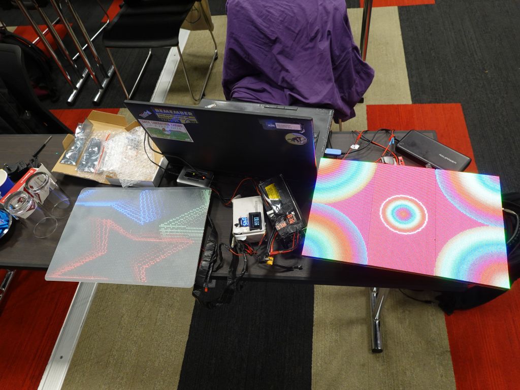
After switching to a new neopixel controller that is directly USB powered, it made more sense to power the panels locally and put the batteries on the panels:
For comparison, the old panel on the left only has the rPi and a small 16B to 5V converter and than relies on that tether cable to the white box on the left which has the DC-DC step down and the ESP32:
finished design with padding, power routing from 3 lipos or 2 USB attery packs
The new version works like the old one, but with batteries directly attached to the panels, which in turn makes them much heavier, but oh well. Video with Lipos and DC-DC converter:
However, the more interesting upside is that I could also replace the 16V lips that get stepped down to 5V, with 5V USB Battery packs. the reason I never did that at the time is that the entire system takes way more than the maybe 2.5A you can get from USB packs on a good day. A somewhat cumbersome workaround to this problem is to use 2 USB battery packs with 2 independent outpus each, meaning 4 independent 5V busses able to put out up to 2.5A depending on the battery pack. So, I split my power system in 4:
front LED panels (3 panels) (1A or more depending on pattern)
rPi (about 1A depnding on CPU load, but must be a nice consistent 5V or the rPi will complain)
Neopixel string run by the ESP32 output if desired. This one might brown out but can be put on a separate USB pack to avoid taking other things down with it
Rear LED panels (also about 1A).
In total it means the whole thing uses about 3A at 5V, or 15W, which means 180Wh for 12h. In theory 2x 99Wh battery packs would work for 10H, but in real life, the first battery pack gets a lot more load since it runs the rPi, so it only really lasts about 7H before I have to replace it. Not ideal, but still nice that I can run from USB instead of lipos if needed:
π
2023-05-17 01:01
in Arduino, Clubbing, Electronics
Version 5 was a bit upgrade with my P2 run rPi run RGB Panels for a resolution of 128x192 per side. The oldest part of the outfit at this point were actually the Neopixel strips I've had for about 5 years, and despite being more reliable WS2813B with backup data line, the PCB traces would break and the chips solder points would eventually break too. The amount of time I've spent fixing and replacing LED strips is more than I'm willing to talk about, but there was just no good alternative, until now.
In the past, flexible LED strands with wires between each pixel did not have enough density, maybe one pixel every 5cm, which was not acceptable for my use. And after many years of waiting, a company finally made P15 flexible strands, one LED every 1.5cm, which looks much better and is even a bit more dense than my previous strips that were P16.6.
Here there are: https://www.aliexpress.us/item/3256804447608449.html . Update, don't buy these, they are shit and broke within hours. See at the bottom
While I was at it, I added a small programmable 16x32 panel to my fanny pack, because why not (the existing fanny packs didn't have sufficient storage, so I ended up decking out mine), and here is the end result:
I have no idea how reliable the strips will be, and unfortunatley they are WS2811 without the backup data path that WS2813 had, but time will tell. I'm bringing it to EDC and we'll see what happens :)
Update: these broke within hours, they were crap.
Version 6.5.1: Ray Wu Strips
Update #1: after the terrible failures of the first strip from the first vendor (the internal wires broke almost instantly), I picked this new one from Ray Wu: https://www.aliexpress.us/item/3256805296356090.html
It ended up being more solid, but the flexing and occasional pulling on the bare strips that were attached with safety pins (I didn't want to glue or sew because it would then be unwashable), eventually caused the strips to fail, although it was more slowly. It worked for 4 festivals in Europe and required some resoldering, but it was not terrible. Still, it wasn't a long term solution either.
Version 6.5.2: Full LED Tubing Protection
So, I tried one more way to do it, this time I put the LED strings inside water tubing of the exact right diameter (fishing them in was a bit tricky), hot glued them on each side, especially the side they are soldered to RC servo connectors which I use for all the electrical wiring.
The next challenge was how to fasten this, and clothes safety pins didn't do the trick, so I used rolls of velcro cut to the right size, and the glue is so good that I was able to glue the velcro strips directly to the fabric. If somehow it won't hold, I'll superglue it.
End result looks like this:
This is now going to burning man, I hope it will hold, especially with lots of biking :)
π
2020-05-04 01:01
in Computers, Electronics, Linux
While I wrote this for my Lenovo Thinkpad P73, this is likely equivally relevant to P53, P72, and P52.
Thinkpad P73 vs P70, not a win all around: only one 2.5" drive instead of 2, and a badly designed power system
So, when lenovo came out with the Thinkpad P70, I wasn't very happy because if you had a 90W power supply, it refused to charge from it, at any rate whatsoever. I was not impressed, but eh, at least it would still power the laptop so that its batteries didn't go flat while plugged in.
Well, leave it to lenovo engineers to make things worse the for the P73. The minimum power supply was raised from 135W (170W recommended) to 170W (230W recommended) which is understandable, but lenovo decided to ensure that the laptop will not take any power from any power supply that does not identify itself as 170W or more. This means that even ifit only needs 40W to sustain itself without digging into the batteries, it will completely refuse to use a 90W or even 135W power supply for anything at all, and kill the battery instead. Lenovo, you just plain suck, there is no excuse for this.
P70 vs P73, they look pretty similar
*Update*: it seems if that if you get a cheaper nvidia chip with the P73, it is then configured to accept 135W power supplies as the minimum required. That said, it will still refuse to work with any regular 90W power supply or external battery back, unless you force it with the center pin resistor swap.
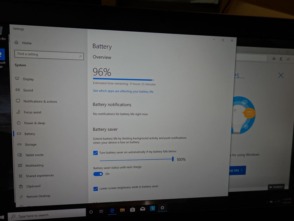
While I have no plans to use windows on that machine, I thought I'd just try it out to see how it does on power. This is where I was impressed, windows can idle at less than 10W for more than 11H runtime, while I'm lucky if I can get linux at 15W. This is definitely a place where linux should do better, of course, it's not as if Lenovo put any work into making linux more efficient on their hardware either:
*Update* : with tlp and using the nouveau driver just enough to turn off the nvidia chip, I'm now able to tune the laptop down to 10W, almost matching windows.
See tlp issue 494 for details on how to setup tlp to run in low power mode when power is plugged in.
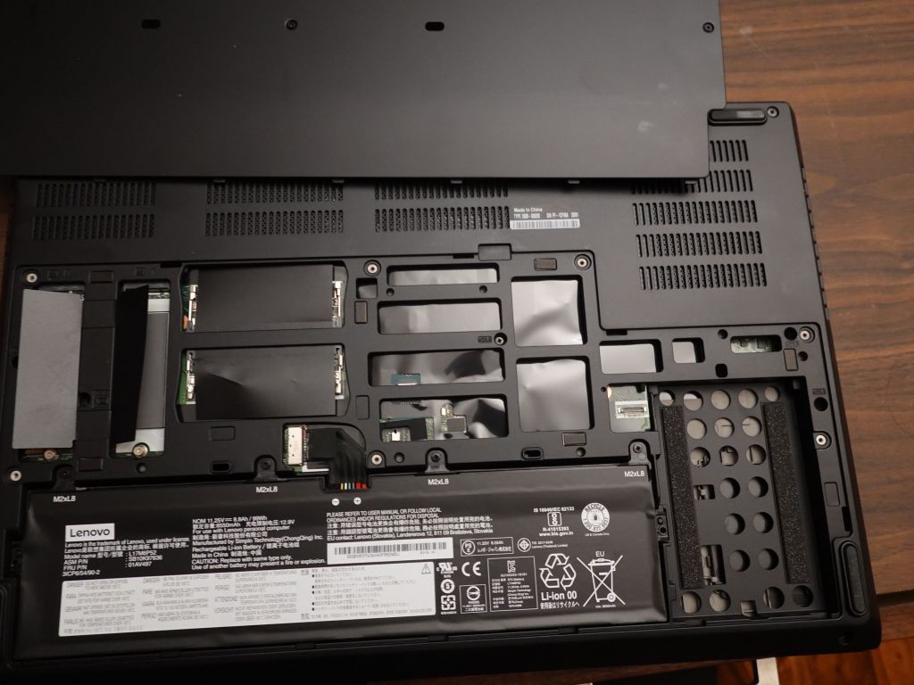
Another disappointment is that the P73 is mostly the same size and weight than the P70, but it has less room for storage. It has a bunch of empty spaces that aren't used for anything, and it can't use two 2.5" SATA drives anymore, like the P70 could. Worse, the now single 2.5" slot uses a lenovo only ribbon cable that does not ship with the laptop and basically means you cannot even add a 2.5" drive without that special ribbon cable, which isn't in stock yet. Well done... Ah yes, the battery is also not hot swappable, even if it is replaceable (unlike a Mac laptop where everything is sealed shut).
this shows the unobtanium lenovo cable for the now only single drive that fits, along the unused space
Ok, stop complaining, just buy a bunch of 170w or 230W power supplies and move on with your life
Well, yes and no:
I literally have 10 power supplies between home and work, not really looking at replacing all 10. Lenovo wants $137 per power supply by the way, even if they are $85 from other sellers
those 170W/230W power supplies are huge. They also weigh as much as some small notebooks (!)
I have 12V to 20V car adapters, those won't work anymore
I have external battery packs for extended runtime, and I haven't found a single one that can deliver the amps a P73 tries to needlessly require
Tricking the P70 and P73 into accepting a power supply it wouldn't otherwise use
Lenovo uses the a center pin resistor to know how much power they can draw from the power supply, see: http://www.thinkwiki.org/wiki/Power_Connector .
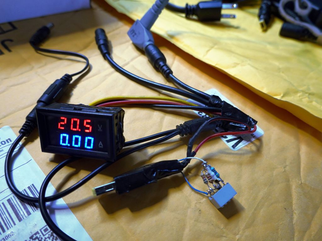
For the P70, I built this power supply adapter with a resistor bridge to tell the laptop how big it should think the power supply, is:
It's basically a configurable version of this. Yes, lenovo, I thank you for the hours I wasted opening up power supply plugs and replacing the center pin resistors:
Here's how the P73 responds:
- 230W works fine   4.6k => I have seen power supplies work with 170W but fail at 230W, so the laptop does draw more
- 170W works ok     1.9k (1.8k also ok)
- 130W rejected     1k
- 90W  rejected     550
The rejected power supplies will be used to charge the laptop if it is shutdown, but they will not be used in any way otherwise. On the P70 the laptop would at least use the power supply to keep the laptop alive, and use half battery half external power supply. Not so with the P73, it just ignores it entirely.
This is utter bullshit as I have plenty of 90W power supplies, including 12V car converters, or a 90W external 20V battery pack I can't use anymore.
You can go read my Hacking a thinkpad slim tip adapter to output more than 90W (required to charge a Thinkpad P70) page for details, including this nice battery pack I couldn't use anymore:
*Update* : so, actually with some serious tlp hacking (basically I told it to force battery mode even if a power supply is plugged in), I've managed to throttle the laptop enough, even when plugged in, so that it only uses 20W. At that point, I'm actually able to use my old external battery pack, as well as a 90W power supply, as long as I lie to the laptop and pretend they are 230W power supplies with the resistor trick. In my tests with windows, it was not possible to throttle the laptop enough when plugged in, not to have it overwhelm a smaller power supply (not that 90W is small for a laptop that normally uses 20-30W when it's not charging batteries).
If you scroll to the bottom of the page, you'll also see a terrible buffer lipo hardware hack I did that allows to use the battery pack with higher amp draws, but it's a bit ridiculous (and bulky).
See tlp issue 494 for details on how to setup tlp to run in low power mode when power is plugged in.
Without the tlp hack or the buffer lipo hack, when I lie to the laptop and tell it is connected to a a bigger power supply, manage power draw with what I run, and disable battery charging in software, but the laptop will still draw the power supply for over 100W when you plug it in for a fraction of a second, and refuse it if the voltage drops.
Obviously this would not be a problem if the laptop simply had a 90W power supply mode where it throttle things down and turned off battery charging. This is mostly what the P70 does.
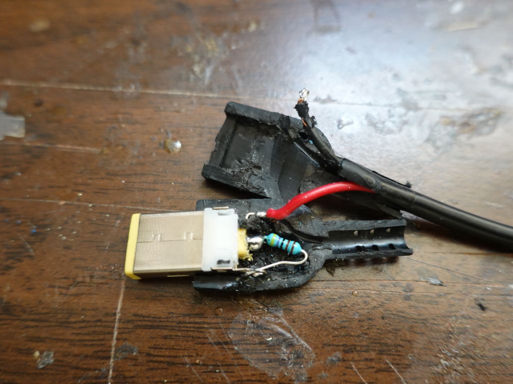
In the meantme, on top of hacking my power supplies, I also made this for my laptop, it looks silly and makes the thinkpad not look like a professional laptop, but well, that's lenovo's fault:
this takes any power supply and replaces the center tip resistor with a 1.9k one to emulate a 170W power supply
From talking to Lenovo, they don't think that this is really a problem, so since I'm an engineer, I made my own external battery pack, but I otherwise recommend to road warriors to avoid thinkpads from now on, given the backward power design in this one.
Making a Thinkpad P73 compatible external battery pack
I did some testing and confirmed that the laptop is very picky about power supplies. It even rejects a 19.7V 20A power supply I had, because it's 19.8V and not 20V. Same thing for amps, it needs to be able to draw maybe around 5A for a short time to accept the power supply (they sure are putting a lot of effort into making sure the power supply is not under-spec'ed).
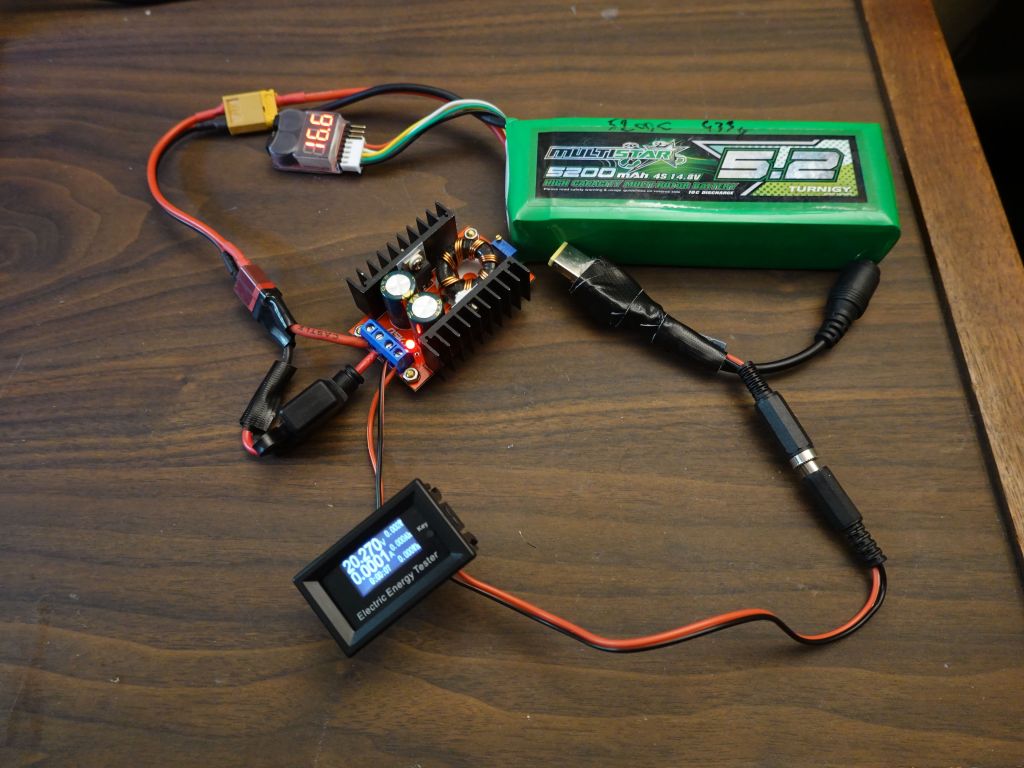
Prototype with 150W step up converter which takes my 16V lipo to 20V while delivering enough amps to make the laptop happy:
it works, and the laptop thinks it's connected to a 230W power supply thanks to the center pin resistor.
Here's a quick demo:
Version 2 was to have a way to recharge the battery pack while it's being used. I've used this to use the battery pack as a buffer to absorb peaks from the laptop without tripping an external power supply, including in a car limited to 100W or a plane power supply limited to even less:
this works in theory, but the lipo charger is quite slow and wouldn't keep up for long, but I made a better version shown lower down
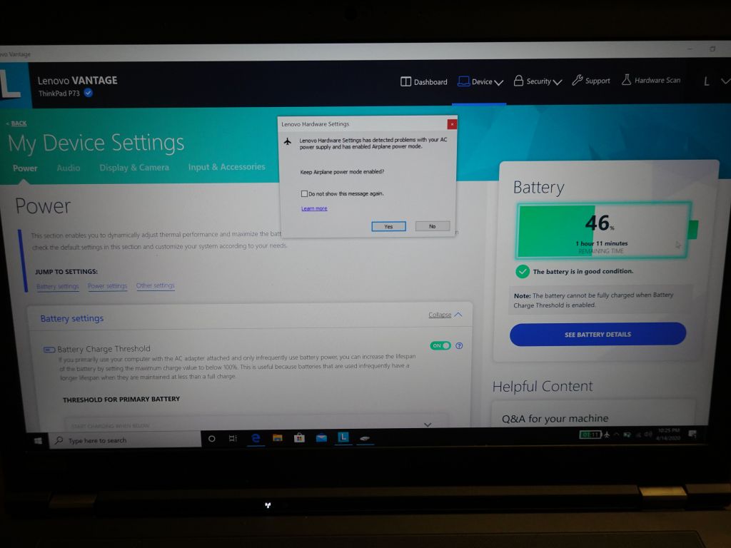
Lenovo's P73 airplane mode simply stops using the external power supply and reverts to batteries. Sigh...
Oh yes, let's talk about airplane mode. The lenovo engineers thought of everything: if they detect that the power supply drops a few times in a row, they offer a nice setting which is supposed to make the plane more airplane friendly. How friendly you ask? Well, you could throttle down the CPUs, disable battery charging, do smart stuff like that. Or, if you're lenovo, you can have airplane mode simply refuse to use the power supply altogether. Thank you lenovo, you wrote a feature that saves me the trouble of unplugging an otherwise perfectly good power supply that you refuse to use (to be super clear, my 230W power supply is plugged in and airplane mode just disabled it):
Making a battery pack to act both as buffer for a smaller power supply, and as emergency external power (even power the laptop from 12v)
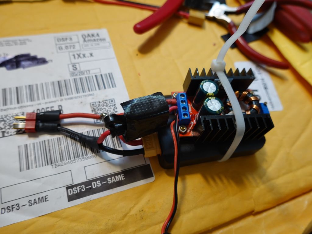
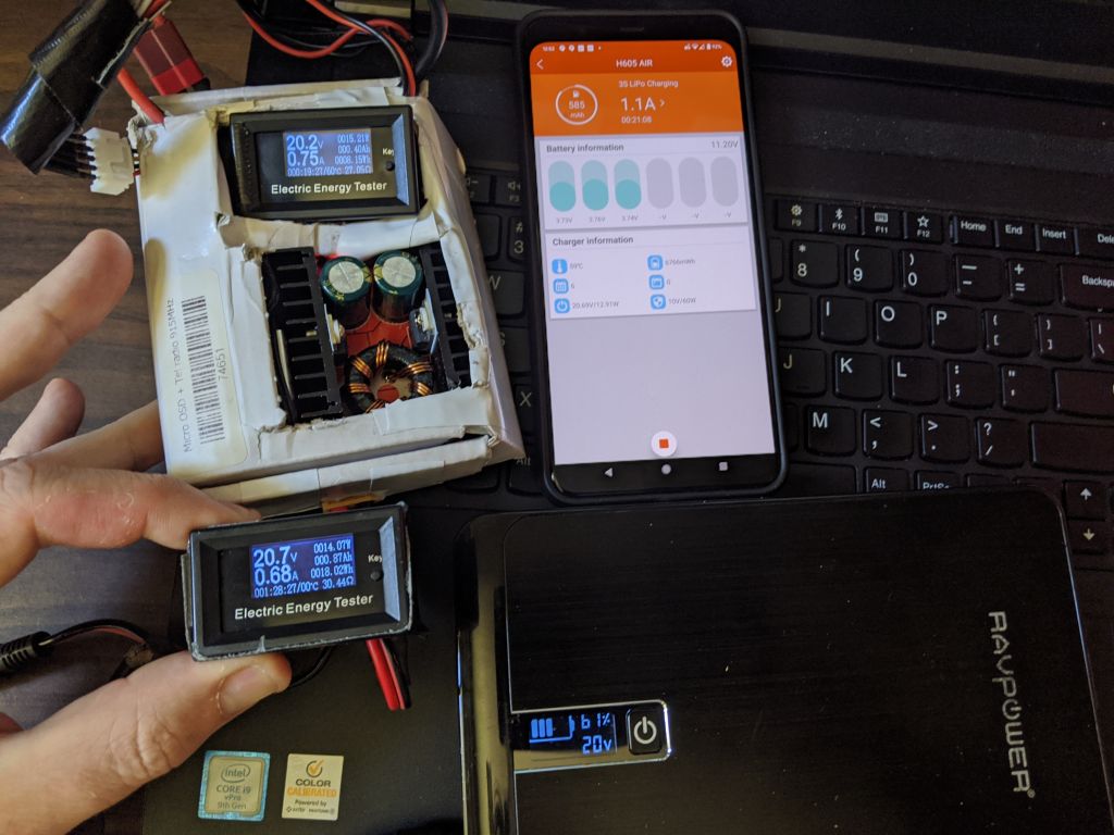
Anyway, back to the battery pack, I found the ISDT H605 Air lipo charger which is small enough and can charge the lipo at 5A, which should be enough to keep up with the laptop when not doing CPU crazy stuff. This also allows using a 12V power supply or a lower wattage lenovo power supply to recharge the pack while it's in use, or not:
version 1 was a bit bigger than I wanted, 90W power supply shown for scale
here, the 90W power supply is recharging the battery at 2.5A while it's being discharged at 3A on the output side, using the battery as buffer
I made version 3 a bit smaller, with a built in 12V lipo to act as buffer for a smaller power supply. Yes, it's a beautiful piece of art, I know :)
Pushed to the extreme, I can now use my original external battery pack again by having it recharge my lipo+150W step up that can output more amps than the ravpower pack can. Of couse, it's inefficient, the ravpower pack outputs 20V that gets down converted to 12V by the H605 Air lipo charger, which charges the built in 3S lipo in the box, and then gets up converted back to 20V without the amp limitation (the phone used to control the lipo charger also inside the box):
The really cool thing is that by using tlp, it's actually possible to tune the laptop down to very low power use, even when plugged in, something that windows probably can't do:
7.3W with the screen off (and around 10W with wifi off and the screen on low dim) is not bad for a laptop that big
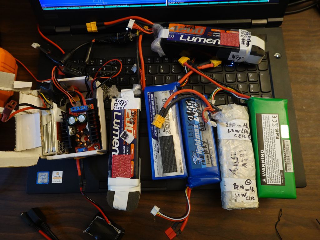
4S Lipo vs 4x 18650 or 26650 batteries
I do have a few lipos laying around, so that's free energy for my laptop if I'm willing to carry them. I have however found that for higher draws, the step up converter doesn't quite keep up at 20V/5A+ with just 12V input (3S), but is fine with 16V input (4S):
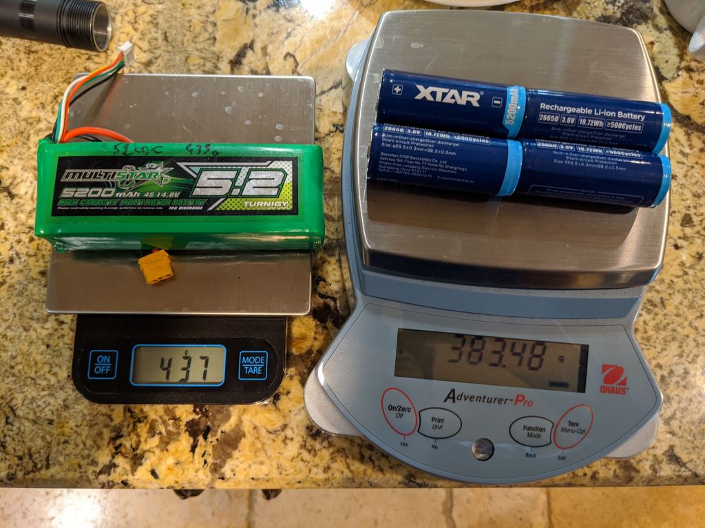
That said, as I recently found out that 16650 (or better 26650) batteries are both lighter and smaller. The only thing the lipos do, is offer a better discharge rate, but while that's useful for a high power RC plane motor that can empty the batteries in 10mn, it's not needed for a laptop:
Outside of 26650 batteries, there are other ones like https://www.18650batterystore.com/21700-p/samsung-50e.htm .
26650s are 195 Wh/kg while the lipo I gave was 184Wh/kg. The 3rd battery listed is supposed to be 260Wh/kg which is much nicer, that said, it looks like those samsung batteries are actually smaller than 26650s, lighter, and yet offer the same 5Ah at 3.6V. If so, that's very impressive.
As of this writing, I have however not found 26650 battery holders that hold 26650 protected cells that are a bit longer. This seems to the be only one available, and it's too short to hold the batteries: https://www.amazon.com/gp/product/B074GVPWSH
A few months later, I ended up cutting them and taping them to make them longer. It doesn't work great, but it was enough for a few tests. In the end, I found that somehow I wasn't getting enough amps out of them, which surprised me, so they didn't work that well compared to a lipo:
Conclusion
Lenovo, please make the P73 work like the P70, and fix this airplane mode thing that turns off the external power supply. That's embarrassing...
Iwas interested in getting a decent amount of amps from my car while it's parked at home if I'm in a power emergency situation (i.e. no power) for maybe 2-3 days (as sadly is now a new "normal" in california).
I knew that this could void the warranty on some parts of the car. I was ok with that. Tesla wants me to buy a powerwall, but I think powerwalls are stupid.
I'd need to spend $30 to $40K in powerwalls to get the same amount of energy I already have in my car and I already paid for. Sorry, but I'm not spending that much for something I may need once every few years. Load shifting my solar in california is otherwise a straight loss, and PG&E forces some silly rules about not allow using powerwalls for time of use power arbitration if you accept the buying credit for them. You get penalized for helping take the peaks off the grid, yeah bureaucracy!
If tesla sold a powerwall that would allow using your car as a battery source for emergencies only (car batteries are not designed for daily cycling like powerwalls), I'd be super interested, but they do not, so I decided to make my own answer.
I knew that I could probably only get 2-3000W out of my car, honestly for emergency use (a couple of fridges and essential equipment), that's good enough. Sure, it wouldn't power all my house lights, or even my furnace for heating (which happens to use over 1000W just to run the fans), but eh, it's for emergency use only, so good enough.
Plugging into the standby 12V battery
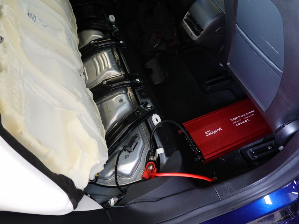
What I knew from the beginning is that the battery in the car is way too small to power a proper size inverter (I have a 3000W one to be safe but honestly I only plan on using 1000W peak for my fridge and an average of 200W otherwise when the fridge is on). What I didn't know is that the Model 3 only provides trickle charge power to the battery, enough to charge it for normal use in the car, but not enough to recharge it if you plug a reasonable inverter into it (it will discharge quicker than it can recharge).
My plan was to connect a big GLA 12V battery in parallel with the car's battery, so that it could absorb big peaks and buffer a it longer in case the car's battery recharge didn't kick in quickly enough. I did however confirm that the car's DC-DC system only recharges the standby battery at a slow rate, so it was not adequate for my need.
Plugging into the cigarette lighter adapter
For some uses, it would work to use some DC-DC charging system to recharge a big 12V battery external to the car and try to keep the car awake as much as possible so that the 12V CLA port stays on. The only issue with that plan is that you can only get about 12A sustained from it, so if you are planning on using over 100W average, this will not work in the end. In my case, my fridge was more in the 200W range.
Tapping into the car's DC-DC system
This is where things get interesting. The car's battery pack is in the 400V range, and 400V DC will definitely kill you (DC is actually worse than AC), so don't even think about messing with that unless you are truly a trained professional.
For the rest of us, what you need to know is that the car has a DC-DC converter that turns 400V into 14V DC. This is used to power the car's systems when it's not sleeping, as well as recharge the small 12V battery that keeps things alive when the car is asleep. The idea is to tap directly into that 12V system which I'm told can provide up to 200A/2000W (which converted to 120V is really only 20A). A few things to note:
The 12V tap is available under the rear seats which you can remove by pushing to clips sideways
Connecting to ground is easy, connecting to the 12V pole is a bit more tricky. It's best to leave the current cable in there as it needs a perfect connection to conduct all the amps it's meant to carry. You can however add a 2nd connector on top of it an add a second nut on top (the bolt it long enough for this, and it seems to be purposely so)
If the DC-DC senses a short, it will shut down to protect itself. This is good, but also bad. The problem is that after it shuts down, it doesn't reset easily, or at all. Once it's shutdown, your standby 12V battery will discharge without being recharged, until it dies. You can recharge it with a 12V battery charger, but obviously this is only a temporary measure
If your DC-DC converter does not reset, you need to disconnect the 12V battery entirely, causing the entire car to shudown and reset. When I did that, my DC-DC converter came back online
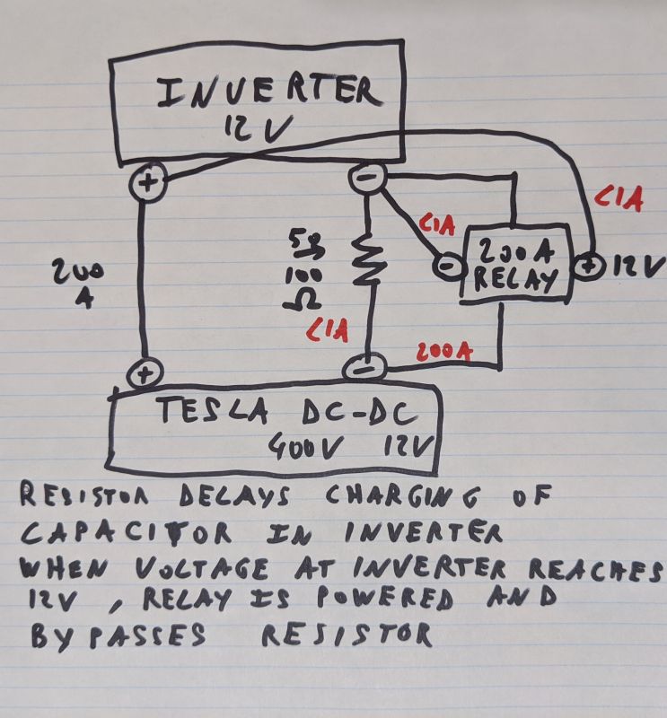
Where it gets interesting, is that inverters come with a big capacitor to allow for transient loads. Those capacitors will take almost infinite energy when you connect them, causing a big spark, and looking like a short, causing the very undesirable shutdown explained above.
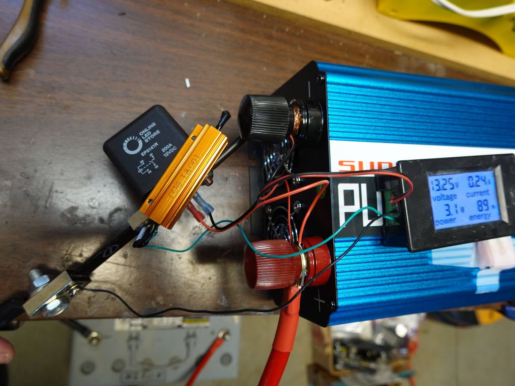
The solution is to wire a big resistor in front of your inverter so that it can charge its capacitor slowly
Then add a 200A relay to bypass the resistor when the inverter is 'charged'. The relay can be powered by connecting it to the inverter itself on the 12V side, making it so that when the capacitor is charged, the voltage across the inverter poles is high enough to actuate the relay and bypass the resistor.
The 2 white holes are where the clips that you need to release. are located. You can also see the black and red tap points:
The Nut on top of the positive bolt under the seat
You could unscrew the existing nut and put your wire there, but it's better not to disconnect the car's 12V power, but there is enough space to put your wire and a 2nd nut on top. You need to get an M8x1.25 (thanks Zack for measuring this).
Building it up without resistor and protection relay
Some inverters are actually polite and do not grab 200A+ as soon as you connect the wire. If you have a spare battery, see if the inverter creates a spark when you connect it the first time. If it does, it's bad news and will want to slow down the current with a resistor, and which is tricky (see below). It could be 1 Ohm, or 100 Ohms, really depends on the inverter.
If you do not see a spark, you may just be able to connect the inverter dirctly to your car with just wires (although if that doesn't work, it will trip the DC-DC converter in the car, and require a full car reset to bring it back online).
Building it up
If you do have a spark when connected to a battery, you'll have to play trial and error with resistors. If the resistor is too big, too much voltage will drop, you'll never get 12V across the inverter and the relay will never activate (which is what you seem to have). If the resistor is too low, too many amps will flow and the DC-DC may trip, requiring the full reset
trip.
I used this:
150 Ohm 25W resistor: https://www.amazon.com/gp/product/B07C1VGNFF . Ok, this one is tricky, maybe your inverter will require a 50 Ohm one, or a 25 Ohm. There is no right answer that works for all. You could buy 4 or 6, and by putting them in parallel (4 will drop 150Ohm to 32 Ohm, 6 will drop it down to 25 Ohm).
resistor limits current and starts charging the capacitor in the inverter, slowly bringing the voltage across its poles from 0V to 12V
voltage across the inverter starts rising until 10V or whatever
once it's enough, the relay is energized and bypasses the resistor. If the resistor it too high, you will not get 12V and this step never happens. you can use a voltmeter to check. If that's the case, add resistors in parallel until it works.
now 200A can go to the inverter and no spark/current inrush was created, and your DC-DC converter doesn't shutdown when it turns on
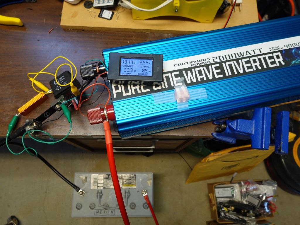
This shows the current meter shunt connected to the bypass relay (which is powered by the connectors on the inverter side). You then see the thick 100W resistor connected in parallel with the relay. This allows current to flow more slowly and ramp up the connection:
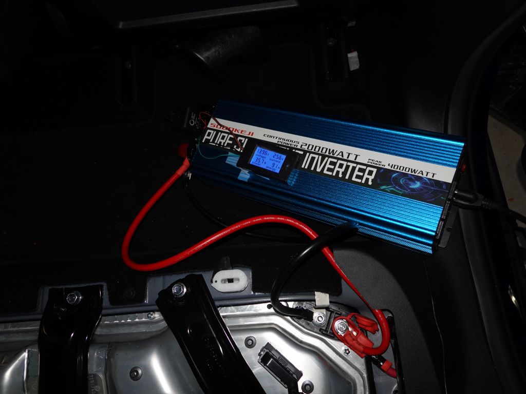
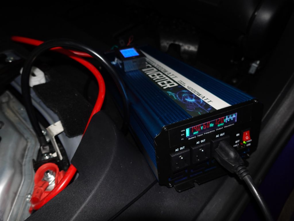
I tested a 1300W microwave which worked without issues, so did my fridge and other devices. The pure sine wave inverter is very important for a microwave, but a cheaper inverter worked well enough for my fridge and basic loads.
Since we're talking about currents of 100A or more, we need to talk about wire gauge. The inverter I got came with 10AWG cables of about 1m. These cables are insufficient for 100A (never mind 200A), but in real life will mostly work for short distances and as long as you don't use the full power continuously (which could technically heat up the cable enough to melt its insulation and cause a short eventually). In my tests with 100A, I lost 0.7V due to inadequate wiring:
0.25V lost in each of the two 10AWG cables (good quality)
Extra wire from relay to inverter lost 0.06V
200A relay only lost 0.06V
100A shunt for power meter lost 0.1V (and gets warm)
Given that the car outputs 13.5 to 14V, this drop is not big enough to matter since the inverter works all the way down to 10V or so, but be mindful of potential heat. Here is the end result:
Keeping the DC-DC system awake
One thing that you still need, it to keep the car from going to sleep if you want the DC-DC converter to stay on. Thankfully a recent software update added camper mode. You can just go in the climate screen/fan icon, set the car in park, and set 'keep climate on' to 'Camp', turn off AC and set the temperature to something low in order to save batteries (i.e. not waste the batteries into climate control).
Another way to keep the car awake is to turn on sentry mode. I think the newer software has sentry mode that uses parking sensors only instead of cameras and computers to analyse frames (if you have parking sensors, not all cars do). I recommend you play with different modes and see if one works for you with minimal battery use
If you know of a more battery efficient way to keep the DC-DC system on without having to run climate or even having the control screens on, let me know (contact Email link at the bottom of this page). Hell, if you build one and get it working, shoot me an Email too :)
Backfeeding your house
If you really know what you're doing, you could use this with a custom made male-male outlet, to backfeed one or both phases of your house (it won't power anything 240V of course). The advantage is that you don't have to run extension cords and power existing lights in your house. If you do this, you must carefully disconnect utility power so that you don't backfeed the grid, as well as potential solar panels that could decide to sync with your inverter and feed more power than you're using, causing other issues you don't want to deal with. Of course, you'll find that 1000-3000W may not be enough power unless you do careful load shedding
I'm not going to give more details because there is definite potential for things going wrong in many ways, but if you absolutely know what you're doing, there you go...
The Frosted Clear Plastic Cutting Mat was good for protection, but didn't offer too much diffusion. Still, it was better than nothing, and that's what I ended up using in the front of my shirt.
The Serenity Foam Underlayment for Laminate Flooring offered better diffusion, but no protection at all. However, I figured out that if I used that, plus the cutting mat on top, I got extra diffusion and protection.
If you wonder, the demos below can be had from:
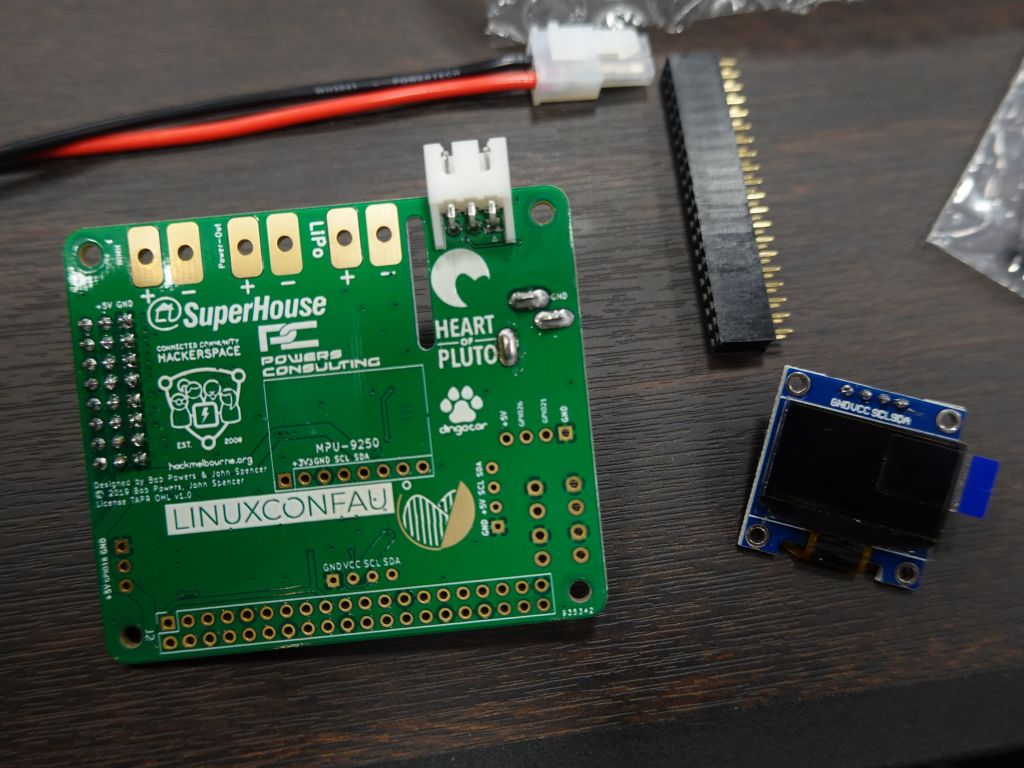
I've been going to linux.conf.au for 18 years now (since 2001), and presented a fair amount of linux talks related there, but the big change for me was the open hardware miniconf that started in 2010. Thanks to its projects every year, I got to learn a lot about microcontrollers and some about electronics.
This talk was my first non linux talk which detailled everything I learned from those miniconfs and projects I worked that stemmed from them. I presented it at LCA 2019 Christchurch.
you can find the talk pdf here: http://marc.merlins.org/linux/talks/Using_Open_Hardware/Using_Open_Hardware.pdf (you'll want this one to get all the clickable links in the slides)
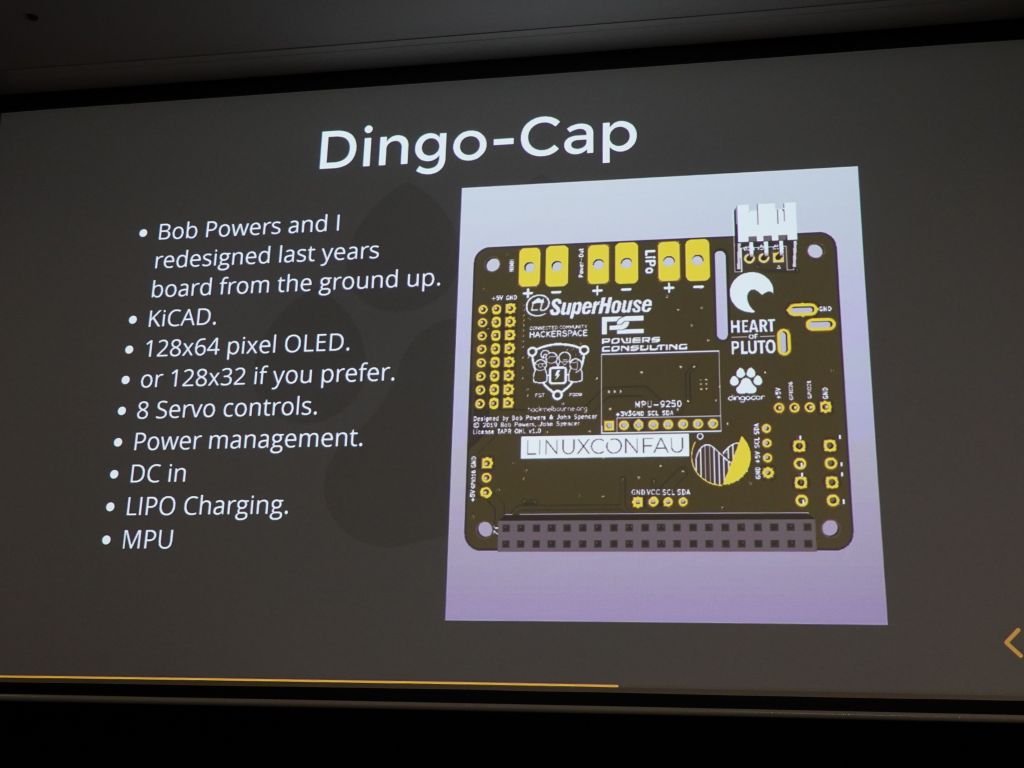
you can view the talk slides in html here or below:
Talk video below:
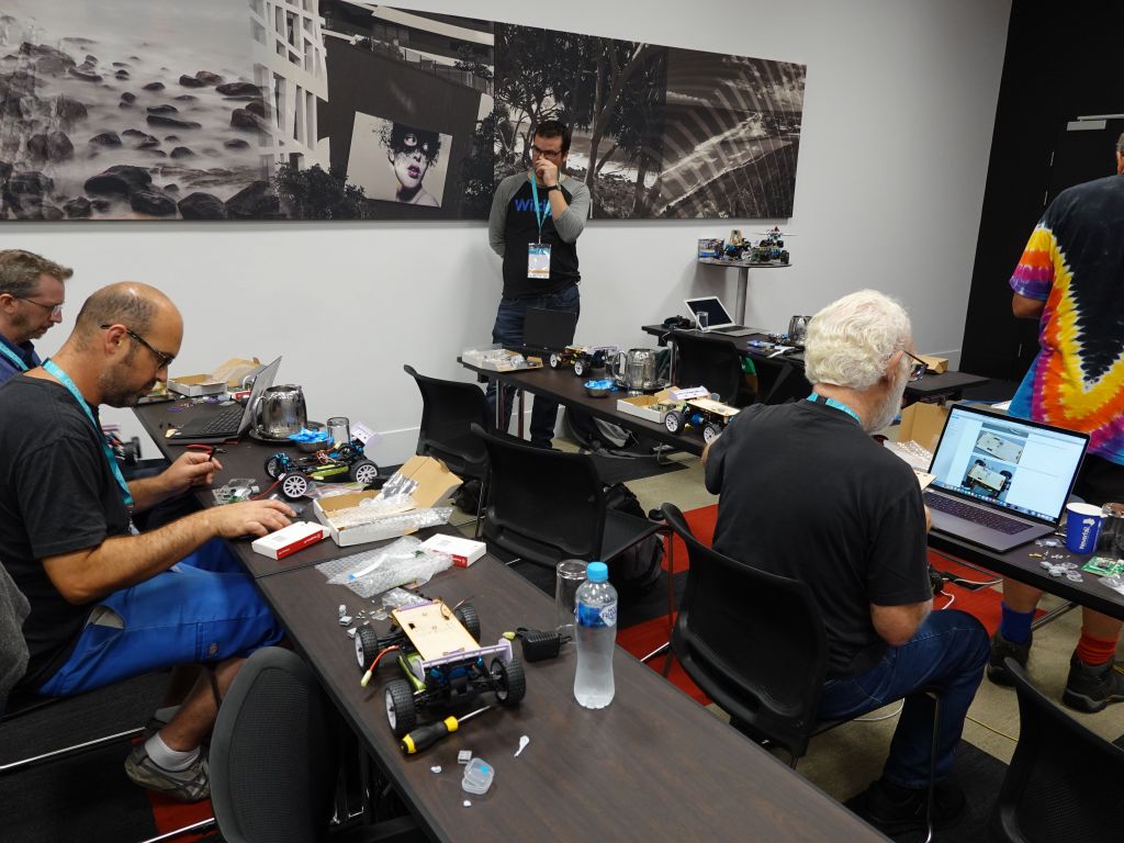
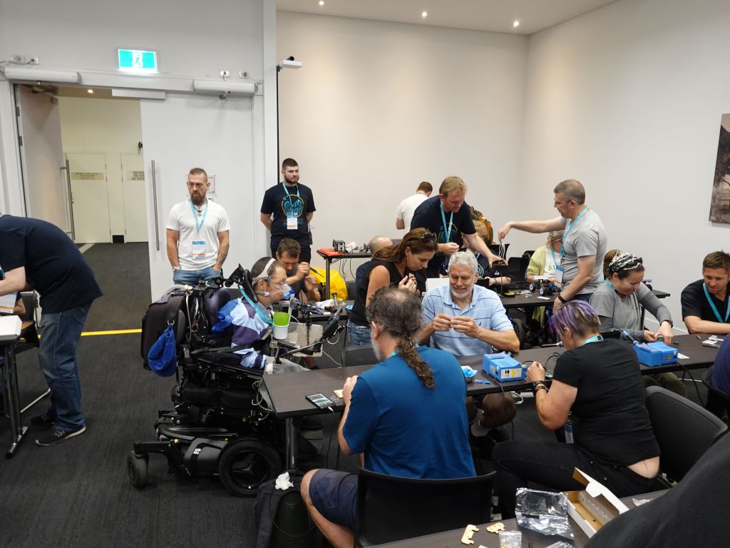
I arrived the sunday before the conference and helped out the open hardware organizers with a bit of last minute setup. I also got to do some last minute testing and tuning of my panels:
hacked up ESP32 with level converters on breadboard to run 3x 64x32 SmartMatrix panels with SmartMatrix::GFX
64x64 P3.8 SmartMatrix::GFX panel vs 3x 64x32 SmartMatrix::GFX P4 flexible panels vs 4x 16x16 FastLED::NeoMatrix P10 panels
After finishing the code tuning and demos just in time, gave a 20mn miniconf talk on the history of linux.conf.au hardware miniconf. I went through how much I learned from those confs and what I was able to achieve as a result. I sure got to learn a lot about microcontroller and driver programming:
I wasn't able to bring my burning man 4096 neopixel matrix, it doesn't even fit in my car, but the irony is that my small 64x64 rgbpanel has the same resolution and fits easily in my backpack
The 64x64 compact display is showing the hand X-ray here
A few days later, I gave the longer version of my talk at the main conference. By then it had grown to over 160 slides in a 45mn slot, or 16 seconds per slide. Ooops...
The full talk went into details on what I learned in the hardware hacking field, a lot of it was simply electricity, U=RI, wires, pre-made components (small inline volt/amp meters, DC-DC converters, and so forth).
and for good measure the talk ends with how I was able to apply some of that knowledge to design simple solutions for hardware testing racks for Google's Fuchsia on arm platforms.
Hopefully the talk and/or slides are useful to you. Links:
When you're off the grid (for many, still true at burning man, or Ephemerisle, you can:
bring big batteries (Li-Ion USB packs and/or big Lead Acid Batteries (AGM is better than car battery)
use solar panels to help recharge the batteries, but most people don't quite realize that panels need to be sufficiently big (and heavy) to charge sufficiently. You also need a charge controller.
use a generator. Generators are quite efficient and cheap for occasional use and make way more power than solar panels per unit of weight. Sadly, they are noisy and not environmentally friendly.
The ideal solution is batteries only if your event isn't too long and you've done the math that the batteries have enough Wh for your needs
Next, is usually batteries + generator that you start as needed. Solar is really the best solution, but it requires more complicated hardware and setup (charge controller, MPPT charger, etc...), but more importantly for any non trivial power need you actually need pretty bulky and heavy panels to handle the load (of course this also relies on you being able to count on enough sun during your event at that location, not an issue for burning man, but potentially an issue for a spring festival in some place that could be overcast or maybe even rainy).
12V Charging
Anyway, back to charging, your best bet is to use 12V lead acid (marine, or AGM are even better), and use DC to DC converters to power all your stuff. For 12V, well, you're done, just plug into that using the appropriate cabling with fuses. You will likely be happy with those two:
Now, some laptops may charge from 5V USB if you're lucky (but that will be slow). Some will charge from USB-C which may allow 12V charging or even 20V charging, but finding such a charger that works from 12V may not be trivial. In the case of my thinkpad, it just plain requires 20V, and not only that, it requires 20V at 5.5A or it will power itself, but it not charge (yes, it is stupid).
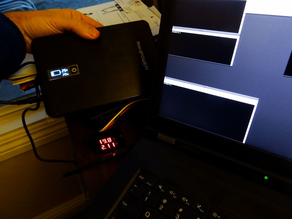
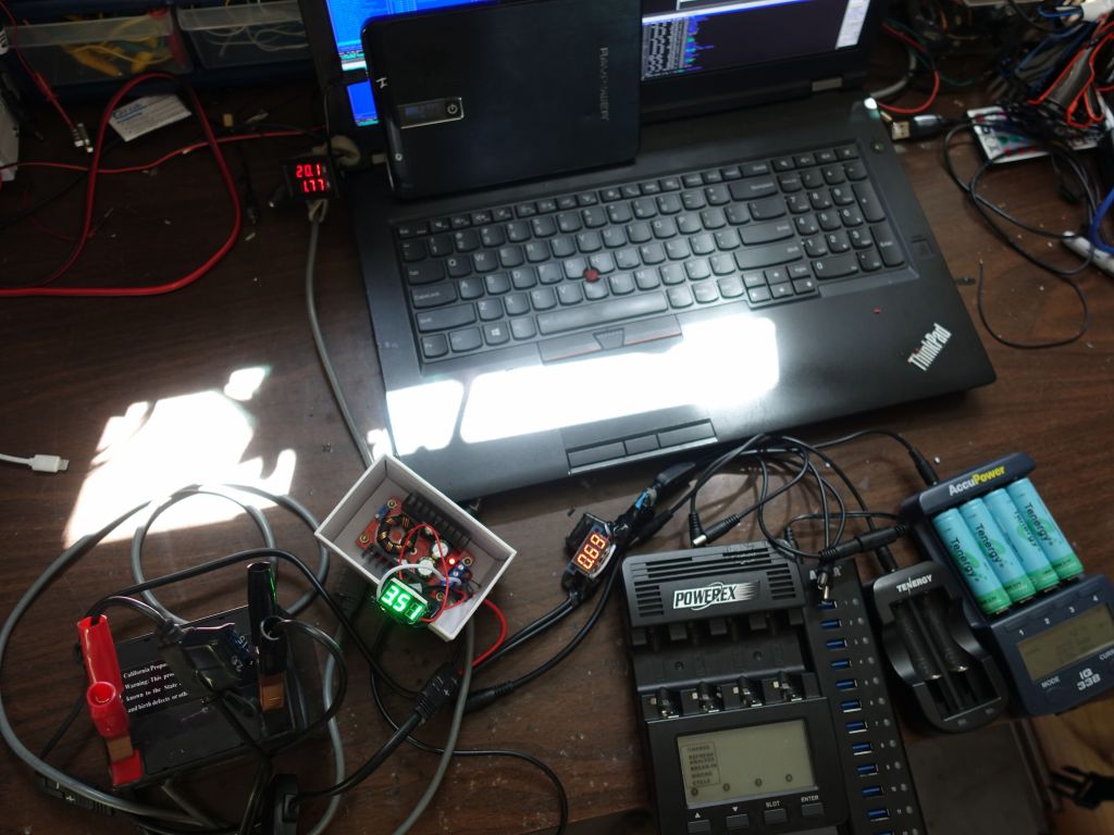
I wrote this page on how to hack a 20V power connection to look like it's at least 135W so that a thinkpad will charge, however I need to upconvert 12V up to 20V with more than 10A from the 12V source. I used a discontinued version of this boost converter, and I also have a 100Wh Li-Ion battery pack that can output enough power to sustain my laptop, but not to charge it. That one also requires 20V to charge (sadly it won't charge from 12V):
this battery pack can output 9, 12, 16, 19, or 20V
You can see the 12V being split and going into the little white box with the step up boost converter. It shows that it's taking 3.5A at 12V and the red display next to the laptop shows it's turned into 1.7A at 20V which goes both into the already charged laptop and the almost charged ravpower battery pack:
it might not look like much, but this is my new 160W laptop power supply :)
5V USB charging
Now, let's look into 5V charging, i.e. USB devices. There are plenty of ways of turning 12V into 5V, that's what all car phone chargers do, but most don't deliver many amps, and don't allow full speed charging for more than 2 or 3 devices on a good day. As a result, I'l recommend this 14 port anker USB hub where you'll ignore the USB part and simply use the fact that it has 80W of charging capacity from 12V input:


")
 is not bad for a laptop that big")


")
