π
2011-05-06 01:01
in Arduino, Electronics
|
When I was getting into Xbee, it wasn't too clear to me what was the recommended interface for the PC size.
While there actually are expensive-ish dedicated PC adapters, the short story is that most folks actually use the same Xbee chips that you put on your arduino shields, and use an adapter that can be connected to USB.
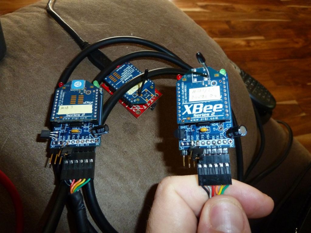
For this you have two to chose from, and I'll explain them both (I got both to try them out, and each has its strong points and weaknesses). This is what they look like (the sparkfun one is red):

Sparkfun
The sparkfun adapter costs a bit more, but it has the built in FTDI chip, so it comes with a mini USB connector and it ready to connect to your PC: no fuss. It also comes with a very handy set of LEDs: serial RX/TX, and RSSI (which shows if RF data was received). The big plus is also that it's already all soldered and ready to use. Oh, the module also easily supports longer Xbee Pro modules.
Its only shortfalls are the lack of AI LED (which comes in handy to show that the module has joined an active network) and no reset jumper, which can be required to blind flash modules or reset modules with ZB END device firmware (which goes to sleep by itself and can't be talked to with X-Ctu without a reset).
Ladyada
Those modules need to be soldered. It's not very hard, but it's time consuming and it's easy to put solder inside the xbee headers. One of my modules wasn't working right until I figured that the problem were the headers had a bit of solder and prevented a consistent good contact. The other shortfalls are the lack of serial RX/TX LEDs which are crutial for knowing that your blind flashing is working, and the default build doesn't accomodate Xbee Pro modules well (you have to bend the resistor and capacitor out of the way like in the picture above).
On the plus side, there is no FTDI chip on there, so they're cheap ($10) and you can use a 3rd party 5 pin adapter cable you may already have, or if you buy one now, you'll be able to reuse it later to flash some arduinos like the AT mega 328.
If you're planning on mostly plugging your Xbee into a breadboard, the Ladyada option is cheaper since you can solder header pins and use the adapter without ever paying for an FTDI cable (or more generally share one cable for multiple modules).
Hardware Reset
Sometimes you have a flash a non responsive Xbee module, it may be a ZB End device firmware that is in sleep all the time, or you just don't know the module speed and don't feel like finding out, you can flash the module with X-ctu and reset the module when it tells you to.
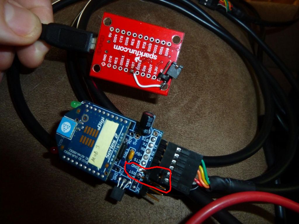
But to do this, you need a reset switch, which neither of those two modules has.
I ended up foldering a PC jumper on both modules as shown in the pictures, and that would be a worthwhile addition to both modules by default.

The procedure for blind flashing is explained here and there:
Set speed to 38400, API disabled
in modem conf, select right firmware
set baud rate in serial interacing option to 38400
set always update firmware and start write with module not plugged in
when error message on pushing reset appears, plug module in |