WARNING: because lockstate is not willing to release anything about the safety of their RF protocol, you should assume that it is vulnerable to both replay attacks (i.e. a neighbour or a van listening to your unlock code, and replaying it later to unlock your door), as well as high speed code sweeps (assume that it is possible to have a custom transmitter transmit all unlock codes in a few seconds and unlock your door).
Actually, the lock is not from lockstate, they simply resell a Taiwanese product from Ez Set which is available through other channels like QVC.
User manual: https://support.remotelock.com/hc/en-us/articles/360001749972-DB-500R-User-Manual
To be fair, many locks are unsafe and can be hacked. Also, the default key lock can likely be unlocked with a bump key, making any fancy unbreakable electronics a bit worthless anyway. So as long as you don't expect a high security lock for $100, let's continue... (but yeah, since I changed their key with a better one that can't be brute forced so easily, I'd feel better if I knew that the RF code can't be trivially sent by a van in the street). It's very possible that Lockstate doesn't know either and only the Ezset folks in Taiwan know.
So, I've been wanting to have a deadbolt (not a lock since electric strikes won't work on my front door), that I can control from my misterhouse PC. For a while smarthome has had an insteon module that talks to Morningstar deadbolts, but it's not a 2 way link: there is no way to know if the door is locked or unlocked.
As a result, I never bought the smarthome/morningstar solution since it was important to me to know that my door wasn't closed right, or closed but unlocked.
Then, I found out about lockstate, and quickly found http://www.lockstateconnect.com/ . A wifi lock, that sounds great, right?
It reports local changes
No wiring required
But, then I read up more about it, and found out it wasn't actually what I was hoping for, nor is it something I can recommend:
It will only talk to their server over the internet. Sorry, but I don't want MY lock to report state and be controllable by a remote company
How well will your lock work if that company is gone in 5 years, or decides to stop supporting their lock (don't think this never happens, it has many times for other companies 5-10 years after the product is shipped).
I want lock updates to go directly to MY server, not theirs.
I want MY server to initiate door unlock right away if needed (that lock will only respond to remote events every minute or so depending on how quickly you want the batteries to die, unless someone pushes a button). This is ok for many uses, but not the 'lock the unlocked door now' required by the bug I'll explain below.
Right, you said lock bug?
Yes. After some testing, I confirmed that there is a flaw in lockstate locks with auto-lock.
If auto lock fails just once, because your deadbolt is not aligned with the hole (happens easily on my door if I push it too far or not far enough), the firmware will remember that auto lock is not working, and not try to auto lock later.
The big flaw is that if you manually close the lock, the firmware is not aware of that fact, and it will refuse to autolock until you either power cycle the lock, or your force a lock event using a motor (either using the lock button on the wrong side of the door when you're inside, or using the remote control for the -R models).
I have notified lockstate of that flaw, but they didn't seem very interested in notifying their customers about it. The fix would include having their CPU read back the microswitches state even when it wasn't given a command (probably having a microswitch event trigger an interrupt that wakes up the CPU and tells it to notice the new state and re-enable auto lock if the deadbolt just got locked ok).
I have personally fixed that problem by having my computer keep track of the lock state and try to re-lock it using the RF remote if it stays unlocked for too long. But understand that without that, you'll most likely end up with the door unlocked sooner or later if you don't close it in perfect alignment every single time.
Proof if you don't believe me (it has 30 second delays since I have my door auto locks after 30 seconds)
Ok, so the wifi lock isn't it. What now?
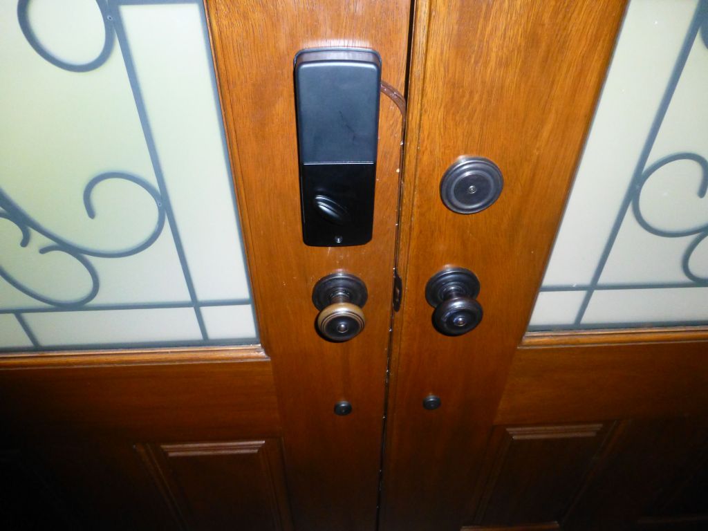
Well, I did go with lockstate afterall, because they did have cheap locks that exactly matched the black color motif of my door, and aesthetics was important for the WAF :)
I bought the Lockstate LS-DB500R-RB (rubbed bronze) because it was a great deal for $100 onsale, and I knew I could very likely hack it to do what I wanted. So, it comes with a remote control, and I knew I could trivially connect its micro switches to a relay and control the door from my PC, just like the Morningstar option, but bypassing insteon and another module I'd have had to pay for.
The more important part however was how to know whether the door was closed, and whether it was locked.
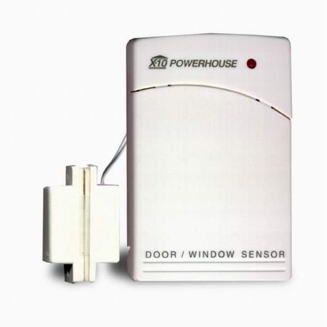
The closed part, I solved first by simply using an X10Sec/X10RF DS10A door/window sensor: http://www.x10.com/security/ds10a_s.html . This is a wireless option working on batteries, and it will fail after 1-2 years when the batteries die, but I already have a fully working monitoring setup with those and misterhouse will tell me when the batteries are low or dead.
Next, I just did not want the lock to require batteries, many comments make it clear that the batteries never last long enough, so I decided to hot wire the door to a power supply.
First, I used a flat phone cable, which I painted, and only found out later that there wasn't enough copper in that cable (just a few thin wires) and it didn't have enough 'oomph' to actuate the motor, doh! So, I put a second thicker cable with enough copper for just the power, using the phone cable for the return path. I just wired the power where the batteries would go if I had put any.
Yes, the wires fit on my door because I have a small gap. Your door may be different
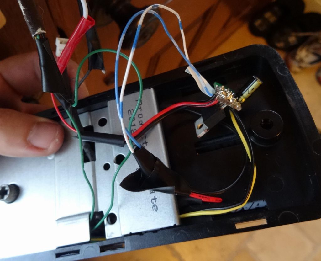
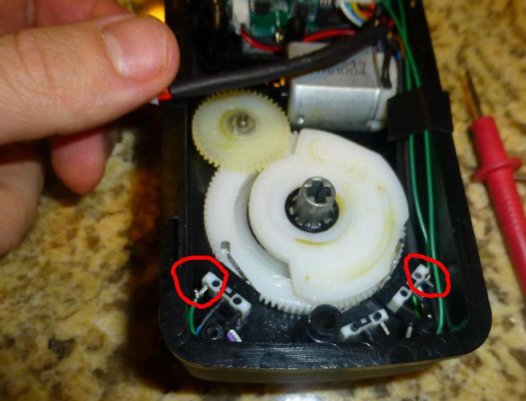
Return path you said? Yes, I found out how to connect to unused pins on the microswitches and know whether the door is locked or unlocked. You can do this easily without even soldering. See picture:
Be very careful not to pull the gears. They are in a very specific place and you'll be sorry if you have to put them back after you lost which way they went.
Now, if you're counting, you'll say that I had 4 wires in my phone cable, and I only used 2 to get the lock/unlock status. It would be nice if the other 2 wires could be used to tell the lock 'lock' or 'unlock', but AFAIK, this is non trivial to do since you don't want a lock to unlock by just easily shorting 2 wires on the board. This is why I got the LS-DB500R with remote control support.
The interesting bit is that the remote receiver is in the keypad, and the keypad actually will tell the lock CPU: "I received an unlock code, please unlock". This does mean that lock/unlock can be sent over the few wires that go through the door, but I'm somehow hopeful that it's not as easy as just shorting 2 wires :)
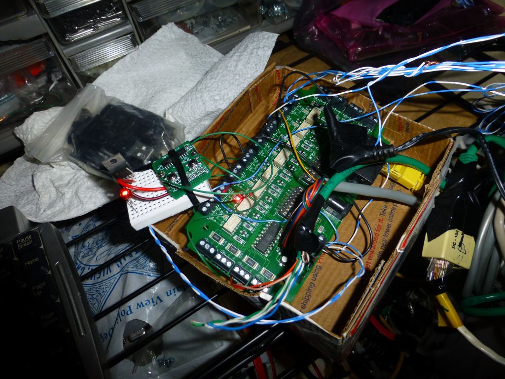
So, instead of explaining in long details, I'll show a few pictures on how to modify the remote control to connect it to relays. I used a small breadboard with a voltage regulator to get 3V from 5V which I have on my 1-wire relay board, and you can send lock/unlock codes by shorting one of the green wires with ground.
note the holes for power wires, nicely labelled 3V + -
finished setup with voltage regulator and power LED (since the remote will not show if it has power)
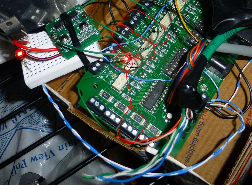
If you look at the above picture carefully, relay 7 is an input relay that gets the 2 wires saying whether my door is locked. Locked shows as LED on. Relay 5 is an output relay to send the unlock command to the remote, and relay 6 sends the lock command. From there, you can watch the video showing how sending the unlock command from my PC (off camera) shows relay 5 going on, then input 7 going off showing unlocked, and later relay 6 going on for lock, closing the lock sense relay and turning input 7 LED back on.
And this is how I got a fully locally controllable lock with lock state sense and door open sense for barely over $100 and a little bit of time.
By the way, if you want to debug RF, the LS-DB-500R (aka Ez Set), transmits on 433.92Mhz.
Last, but not least, the lock has another issue where it locks/unlocks the deadbolt on power reset. This is not a huge problem if you are using batteries, but with house power, that means that a power outage would unlock your door for a brief time when the power comes back up. Not so great... So I hacked mine with a Voltage regulator, put the lock behind it and also connected the batteries behind a diode to give backup power if the wall power goes away (diode stops the wall power from trying to recharge non chargeable batteries):
Also, I figured I'd show the voltage regulator I use to power the door. My original one was a 5V Vreg and it just wasn't enough for the lock. It would often complain that the voltage was too low.
I now use a 6V LM regulator and add a big diode that prevents both backflow and drops the voltage by only 0.3V, giving me 5.7V. The door is very sensitive to low voltage and will complain loudly if your voltage drops to 5V or less. The batteries can give up to 6.2V or so, and their voltage gets dropped to 5.5V by regular diode that drops 0.7V. The end result is that the battery voltage is always lower than the power supply, and the batteries never power the lock unless the power supply is disconnected (which in my case means a power failure):


")