| |
π
2009-12-23 00:00
in Computers, Linuxha
If you are interested in this page, you should also refer to my later Temperature, moisture, humidity, and UV monitoring and graphing with 1wire devices, owfs, and cacti blog post. Temperature logging
I had basic temperature logging via the HAI RC-80 thermostat code I co-maintain which polls our thermostats for temperature (along with other settings like whether they are running). Other info on the RC-80 thermostat can be found here, just note that they cost about $50 used on Ebay.
Our house is a little different from the average: we have a sub-zone in the master bedroom which is basically a second big vent going directly from the HVAC system to the bedroom. The bedroom has an RC-80 which turns on the HVAC system and opens the bypass vent when the master bedroom temperature needs to be adjusted, however there is still air going to the rest of the house too, but since a lot goes to the bedroom, it gets to temperature more quickly. So you may ask why the subzone is not just a separate zone and that's because our HVAC system is too old, cannot be run a less than full power and would get damaged if its output was only sent to our bedroom.

The RC-90 looks pretty simple

the interesting part is the added wires for the serial port
The main zone is controlled by an RC-90 (which I use as a regular RC-80). When it turns on, the entire house gets air, including the master bedroom through its smaller vents.
The little trick is that the zone board (which gets input from both the RC-90 and RC-80) is configured to run both zones for 2 minutes after the heating or cooling has stopped (probably to recirculate the air, even in the unused zone).

HVAC zone board
The one nice thing is that the HAI thermostats tell me what they are telling the hvac zone board, so I can tell when the command was sent, for how long and compare with the HVAC output with temp sensors. The thing that is not as good is that the temperature I get back from the HAI thermostats does not have any decimals (as much as I hate Fahrenheit, I log temps in Fahrenheit because with integer only temperatures I get somewhat better resolution in Fahrenheit than in Celsius).
Here's a good example graph showing combined data:
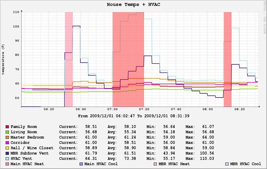
The graph shows the bedroom HVAC being activated (orange) with the resulting rise of both temperature probes since the subzone has to activate the main zone too). When the main zone is turned on (red), the subzone vent only shows a slight rise in temperature due to leakage in the valve, except in the last 2 minutes right after the HVAC system is turned off but the fan left on: you can see the vent being opened right after the HVAC is turned off.
You can compare with the simpler graph based just off data from the HAI RC-90 and RC-80 and data gathered from the misterhouse HAI code I improved. The following graph shows AC being turned on for the main house and the master bedroom after that:
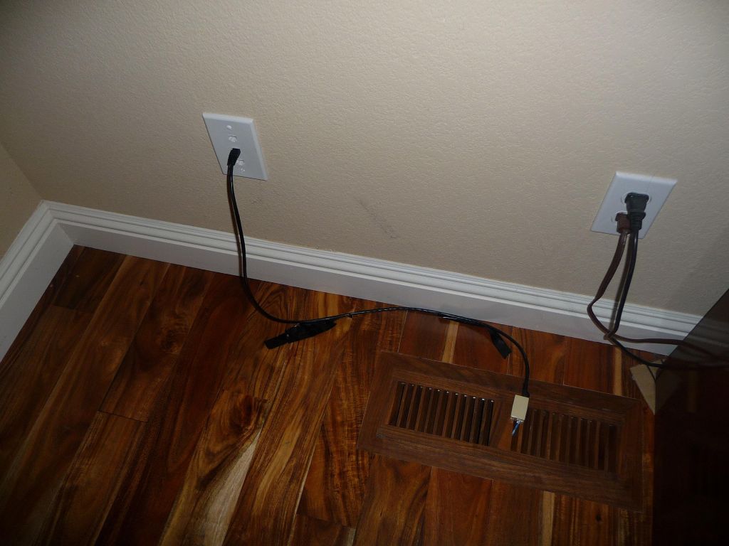
Since the 1°F resolution of the HAIs is not good enough for nice graphs, this is where the 1-wire DS18B20 temp sensors come in. In most rooms I just have them plugged into the wall via Cat-5 (more details below) and in order to save having to make another hole in our ducts, this is how I measure the main duct temperatures when air is being blown :)
Findings
So that's for the HVAC system but after that I was curious to know:
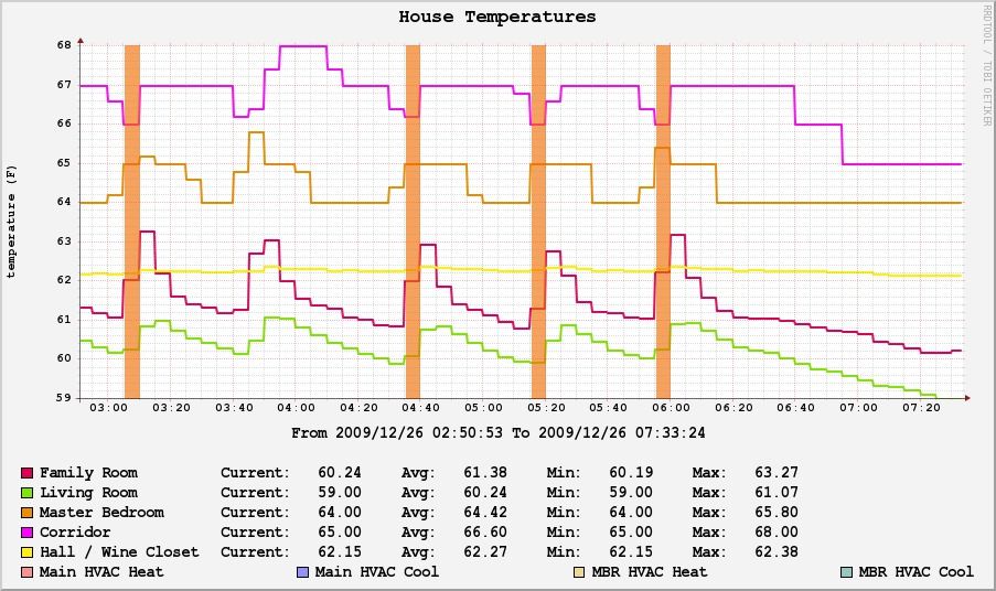
how balanced or misbalanced the hvac system was (which rooms get warmer or colder). In our case, we're actually happy to have a misbalance as we don't need to heat up or cool down all the house evenly. The following graph is telling, it shows that using the main HVAC system gets our main corridor (where the thermostat temp is sampled) warmer than than our master bedroom with the family room being warmer than our living room (which is good since we spend more time in the family room than the living room). Of course, it also shows our family room has more leakage, likely through the fireplace vent. The good news is that the wine closet is well insulated and shows a relatively constant temperature, so I am hopeful that we may be able to hack in an insteon controlled AC system that exhausts to the attic and cools down the wine closet (the only issue is controlling the humidity since an AC system will get the temperature to a nice value, but also dry up the air).
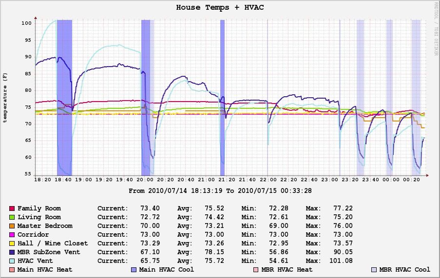
the temperature under the house in the crawl space to know if we can get air from it to cool down the house more cheaply during the summer by grabbing air from under the house during the night. The first graph shows temperatures during the winter on sunless days (roof shingles temps otherwise still get over 90 degrees in plain sun during the winter). The second graph during warmer end of summer days shows that we may be able to get cool air from under the house instead of running the AC (will need HVAC modifications).
If you wonder why the attic and garage lines are squiggly, that's because of the computer closet exhaust fan to the attic and the heat from the fridge compressor in the garage.
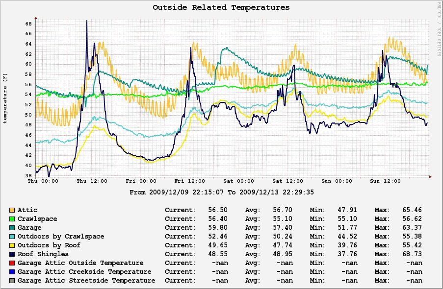
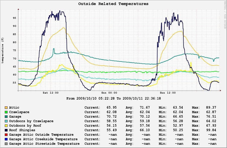
how warm the roof and attic get during the summer is also interesting (the above graphs both show how warm the roof shingles get, how it wouldn't be hard to heat water there, and how attic temperature closely follows the roof temperature even with the exhaust fans we have in the attic)
outside air temperature at the top of the house vs at its base in the shade. It make sense that the air by the crawlspace is less variant and more stale, keeping a more constant temperature, while the air by the roof (sampled under the roof to negate roof sun heating) moves around more with wind.
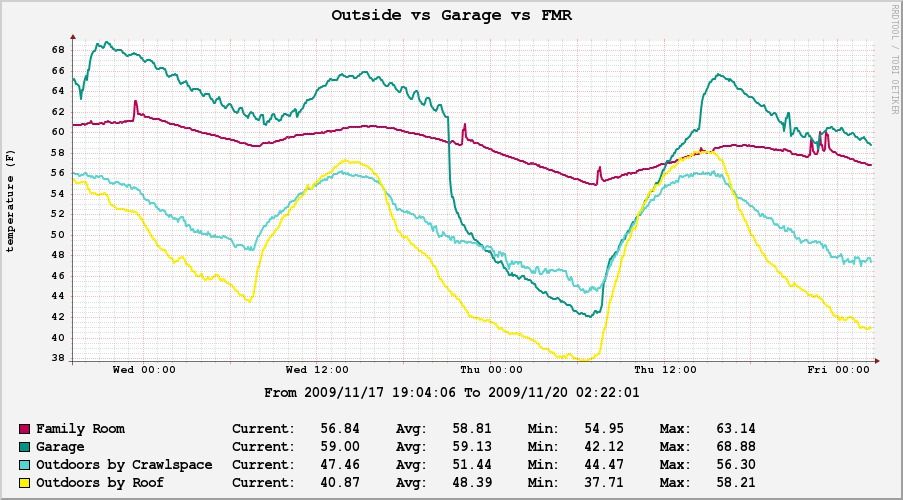
the temperature in our lesser insulated garage and whether that's influencing temperatures in our family room on the other side of the wall, or not. One night, we kind of forgot to close the garage door. This zoom on the Garage vs Family Room vs Outside temperatures graph is relatively good news: the garage temperatures dipped a lot, but thankfully the family room on the other side of the insulated door, did pretty well.
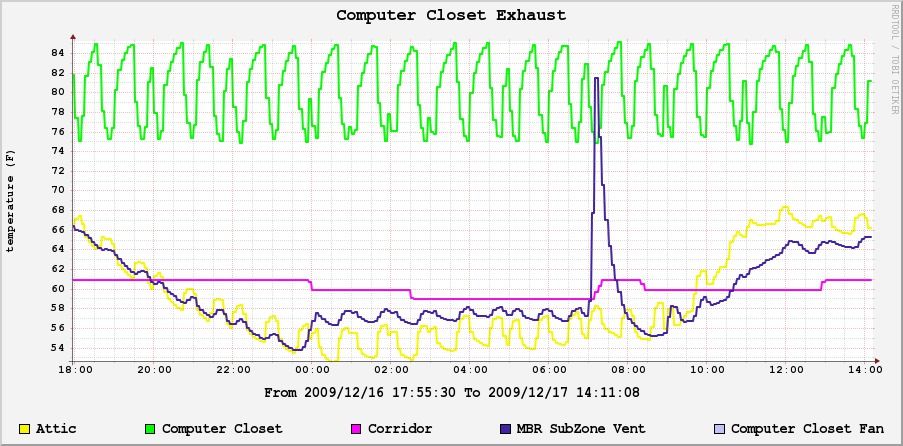
for fun, I looked at how hot my computer closet is getting, and used that temperature to turn the exhaust fan on and off via insteon and X10. You can see the closet temperature cycle between the 2 boundaries I set for the fan. You can also see smaller peaks that are due to my failsafe of turning the fan on every hour regardless of temperature (I have code in misterhouse that checks if the temperature is low enough and turns the fan off, as well as turns it on when it reaches 85F, but it also gets turned on from cron on the hour as a backup if misterhouse or temperature sampling craps out).
It's also fun to see how the attic temperature changes as I exhaust heat from the computer closet into it, and how it even affects the HVAC duct a little bit, showing how those ducts, despite all their insulation, still leak temperature somewhat (the big peak in the duct is of course the HVAC system turning on).
measure the temperature in the main HVAC zone to see how hot the air I get from it is, or how cold air from our AC system is (and do the same for master bedroom subzone). For that, I have the hot air side (115F, which is lower than I thought) but not the cold air side yet since we haven't run the air conditioning since I've had the duct temperature monitoring.
Anyway, that's enough graphs for now, if you want more (and make your own), here is a link to a list of all the graphs. 1-Wire Setup
For temperature logging throughout the house and outside, the recommended solution is to use Maxim/Dallas 1-wire network (which is really 3 wires: ground, signal, and 5V which can be shunted back to ground if you don't need to measure extreme temperatures).
I'm not going to give a full description of everything since others have already done this better than me, but there is a fair amount of outdated information out there, so let me fix some of it (written as of 2009/12):
I went with a DS9097U maxim/dallas 1-wire serial adapter (I originally got the USB based DS9490R-A which is really a DS2490 chip, but I found it was less reliable with long networks, and it would just lock up and require a full power cycle with it had errors). If you decide to go with the USB version, since it is known to lockup with at least digitemp (maybe owfs is able to recover it), you will need to detect lockups and do a full USB power cycle to come back to life (i.e. you need to get a rare USB hub that is externally powered and allows power cycling. See my friend Andrew's blog if you need to get a USB hub that can power cycle ports).

DS9490R-A aka DS2490 USB 1wire adapter plugged in powered USB hub, and DS9097U serial adapter plugged into USB to serial adapter
If you think you should get the USB version because you don't have serial ports, a USB-serial adapter like in the picture above is only $20 or so. I really do prefer the reliability of the serial adapter and picked up a USB to 4 serial port adapter for $45 on ebay.
As far as software goes, you can use both digitemp or owfs. Owfs supports a few more devices and uses a cool filesystem interface, but this requires kernel support. Digitemp works well enough for most cases and is more portable to random devices, including my linksys router. I picked digitemp and will give examples for it below, but owfs is a fine choice too if it works for you.
Where to buy from?
First, you have the option of buying $20 modules that have the transistor looking temperature sensor inside (easier to wire) to just the temp sensor part for less than $5 and you have to wire it yourself. Your call.
A few places I found:
For temperature sensors, I started with the oft recommended DS18S20, but found out that the DS18B20 are actually much quicker to poll, so this is what people should buy today (they are fully compatible with digitemp and owfs). Oh, and the -PAR models are the same but with pins 1 and 3 hotwired so that you don't have to do it yourself (I've found it not necessary to use a more complicated powered network even for my long network, it's only required to sense extreme temperatures which you are unlikely to care about).
Note that all 4 kinds (DS18S20, DS18S20-PAR, DS18B20, and DS18B20-PAR) look exactly the same and work the same with digitemp and owfs. See this page for a comparison of the different sensors and you can read this page on PAR vs non -PAR.
for debugging, I used those cat-5 splitters, which do come in handy when I have to debug the network (unfortunately, the whole 1-wire network can go bad if something is wired backwards or there is a short, and you will lose part of the network if a miswire causes the circuit to be open). This is where they come in handy, the picture below shows 3 temp sensors wired in parallel to the splitter (I also label their serial number on a piece of tape for easier reading).
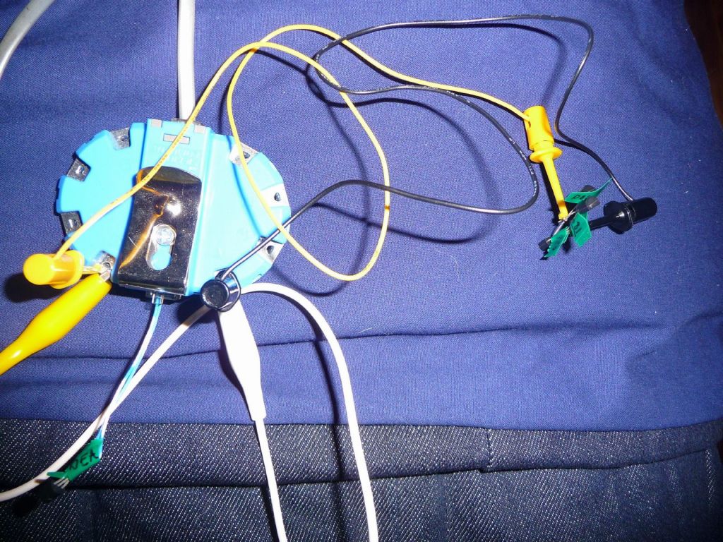
There is a big warning: all phone cords I've found are crossover cables as opposed to straight through, so if you use one, your pins will be reversed and you'll have to wire accordingly. See this picture of the USB 1wire adapter plugged into a DS18S20 where I had to reverse the pins for it to work due to the crossed phone cable:

the center pair is reversed due to the phone cable, the middle pin is actually signal, while 1 and 3 are ground and power shunted together
.
You can find wiring details on this page, or in a nutshell, my cheat sheet below:
pin 2 (RJ11)/pin 4 (RJ45) -> 1-W/DATA (DS18B20 pin  2 )	blue wire
pin 3 (RJ11)/pin 5 (RJ45) -> GND+VDD  (DS18B20 pin 1+3)	white wire

Cat 5 wiring to a plug where 1-wire is looped back from the blue pair to the green pair:
3 1-W back -> green/white
4 1-W -> blue
5 GND -> blue/white
6 Gnd back -> green
Note that the Maxim documentation gives you incorrect pin numbers because they count RJ11 pins in the opposite order from what's standard as per wikipedia.
I personally made my own cat-3 cable with my crimping tool and simple wire. That's the best way to know it's wired right (and you only need 2 wires anyway, the center pair)
I built a network that's about 1000ft long by using existing cat5 cables in our house, sending the signal down one pair, and bringing it back another pair (this doubles the distance, but works for me and saves my buying a 1-wire hub which would otherwise be required for this).

you can see my Cat-5 cables coming from multiple places in the house and being daisy chained together (I use the blue pair to get there and the green pair to come back
The other trick is to keep good track of the DS18B20s serial numbers as you install them since it will be hard to make out what is what otherwise when everything is installed later.
useful links
Digitemp Setup
Update at this point, I would not recommend using digitemp anymore unless you only ever plan on using DS18S20 and DS18B20 temp sensors, as this is mostly what digitemp supports (it does support one single humidity sensor too, but only with the serial interface, not the USB one). Long story short, if you're planning on doing anything more with 1-wire, you should invest the little extra time and set yourself up with owfs instead, which I've described in my later Temperature, moisture, humidity, and UV monitoring and graphing with 1wire devices, owfs, and cacti blog post.
First: why would I use digitemp and log to a file from cron (which I then re-read and process for graphing and other uses) instead of using built in support in misterhouse? The reason turns out to be that I just don't want to lose temperature samples if misterhouse dies or if I'm hacking on it and have it down for a while. Simpler is better and more reliable in this case :)
USB:
On linux you may have to unload the kernel support for this USB adapter:
rmmod ds2490

Then do a quick scan:
gargamel:/tmp# digitemp_DS2490 -w
DigiTemp v3.5.0 Copyright 1996-2007 by Brian C. Lane
GNU Public License v2.0 - http://www.digitemp.com
Found DS2490 device #1 at 003/005
Turning off all DS2409 Couplers
...
Devices on the Main LAN
1080BAED010800EA : DS1820/DS18S20/DS1920 Temperature Sensor
28D813060200000F : DS18B20 Temperature Sensor
812C282900000044 : Unknown Family Code

Then generate a config file:
gargamel:/tmp# digitemp_DS2490 -i
DigiTemp v3.5.0 Copyright 1996-2007 by Brian C. Lane
GNU Public License v2.0 - http://www.digitemp.com
Found DS2490 device #1 at 003/005
Turning off all DS2409 Couplers
...
Searching the 1-Wire LAN
1080BAED010800EA : DS1820/DS18S20/DS1920 Temperature Sensor
28D813060200000F : DS18B20 Temperature Sensor
ROM #0 : 1080BAED010800EA
ROM #1 : 28D813060200000F
Wrote .digitemprc

Here you can edit/save the file, and running -a will use the config file in the current working directory:
gargamel:/tmp# digitemp_DS2490 -a
DigiTemp v3.5.0 Copyright 1996-2007 by Brian C. Lane
GNU Public License v2.0 - http://www.digitemp.com
Found DS2490 device #1 at 003/005
Dec 26 22:26:05 Sensor 0 C: 24.31 F: 75.76
Dec 26 22:26:07 Sensor 1 C: 26.19 F: 79.14
The serial adapter works almost the same way, you just have to specify the serial port until it's written in the configuration file:
gargamel:/tmp# digitemp_DS9097U -s /dev/ttyS1 -w
DigiTemp v3.5.0 Copyright 1996-2007 by Brian C. Lane
GNU Public License v2.0 - http://www.digitemp.com
Turning off all DS2409 Couplers
............
Devices on the Main LAN
10A8D1ED0108009C : DS1820/DS18S20/DS1920 Temperature Sensor
10A8D1ED0108009C : DS1820/DS18S20/DS1920 Temperature Sensor
102223EF0108009B : DS1820/DS18S20/DS1920 Temperature Sensor
1052D1ED01080021 : DS1820/DS18S20/DS1920 Temperature Sensor
10D1D0ED0108005F : DS1820/DS18S20/DS1920 Temperature Sensor
10F9F3EE01080076 : DS1820/DS18S20/DS1920 Temperature Sensor
1045D2ED010800B1 : DS1820/DS18S20/DS1920 Temperature Sensor
10E5E7ED010800BB : DS1820/DS18S20/DS1920 Temperature Sensor
285CFC0502000004 : DS18B20 Temperature Sensor
28DD71C701000024 : DS18B20 Temperature Sensor
283359C7010000D8 : DS18B20 Temperature Sensor
2857B65902000062 : DS18B20 Temperature Sensor
09C7BE600500009E : DS2502/DS1982 1Kbit Add only memory

gargamel:/tmp# digitemp_DS9097U -s /dev/ttyS1 -i
DigiTemp v3.5.0 Copyright 1996-2007 by Brian C. Lane
GNU Public License v2.0 - http://www.digitemp.com
Turning off all DS2409 Couplers
...........
Searching the 1-Wire LAN
10A8D1ED0108009C : DS1820/DS18S20/DS1920 Temperature Sensor
1094A2ED0108002F : DS1820/DS18S20/DS1920 Temperature Sensor
102223EF0108009B : DS1820/DS18S20/DS1920 Temperature Sensor
1052D1ED01080021 : DS1820/DS18S20/DS1920 Temperature Sensor
10D1D0ED0108005F : DS1820/DS18S20/DS1920 Temperature Sensor
10F9F3EE01080076 : DS1820/DS18S20/DS1920 Temperature Sensor
10E5E7ED010800BB : DS1820/DS18S20/DS1920 Temperature Sensor
285CFC0502000004 : DS18B20 Temperature Sensor
28DD71C701000024 : DS18B20 Temperature Sensor
283359C7010000D8 : DS18B20 Temperature Sensor
2857B65902000062 : DS18B20 Temperature Sensor
ROM #0 : 10A8D1ED0108009C
ROM #1 : 1094A2ED0108002F
ROM #2 : 102223EF0108009B
ROM #3 : 1052D1ED01080021
ROM #4 : 10D1D0ED0108005F
ROM #5 : 10F9F3EE01080076
ROM #6 : 10E5E7ED010800BB
ROM #7 : 285CFC0502000004
ROM #8 : 28DD71C701000024
ROM #9 : 283359C7010000D8
ROM #10 : 2857B65902000062
Wrote .digitemprc
gargamel:/tmp# digitemp_DS9097U -s /dev/ttyS1 -a
DigiTemp v3.5.0 Copyright 1996-2007 by Brian C. Lane
GNU Public License v2.0 - http://www.digitemp.com
Dec 26 22:30:39 Sensor 0 C: 16.88 F: 62.38
Dec 26 22:30:40 Sensor 1 C: 8.69 F: 47.64
Dec 26 22:30:41 Sensor 2 C: 13.44 F: 56.19
Dec 26 22:30:43 Sensor 3 C: 16.19 F: 61.14
Dec 26 22:30:44 Sensor 4 C: 10.69 F: 51.24
Dec 26 22:30:45 Sensor 5 C: 13.25 F: 55.85
Dec 26 22:30:46 Sensor 6 C: 9.06 F: 48.31
Dec 26 22:30:47 Sensor 7 C: 15.44 F: 59.79
Dec 26 22:30:48 Sensor 8 C: 5.25 F: 41.45
Dec 26 22:30:49 Sensor 9 C: -8.75 F: 16.25
Dec 26 22:30:50 Sensor 10 C: 17.25 F: 63.05
The trick is to save your .digitemprc in /etc/digitemprc, and then I call digitemp_DS9097U -a -c /etc/digitemprc | /var/local/scr/digitemp_rename.
Below are my configs:
gargamel:/tmp# cat /etc/digitemprc
TTY /dev/DS9097U
READ_TIME 1000
LOG_TYPE 1
#LOG_FORMAT "%b %d %H:%M:%S Sensor %s C: %.2C F: %.2F"
LOG_FORMAT "%Y/%m/%d %H:%M:%S Sensor %s F: %.2F"
CNT_FORMAT "%b %d %H:%M:%S Sensor %s #%n %C"
HUM_FORMAT "%b %d %H:%M:%S Sensor %s C: %.2C F: %.2F H: %h%%"
SENSORS 14
ROM 0 0x10 0x22 0x23 0xEF 0x01 0x08 0x00 0x9B
ROM 1 0x10 0xA8 0xD1 0xED 0x01 0x08 0x00 0x9C
ROM 2 0x10 0x94 0xA2 0xED 0x01 0x08 0x00 0x2F
ROM 3 0x10 0x52 0xD1 0xED 0x01 0x08 0x00 0x21
ROM 4 0x10 0xD1 0xD0 0xED 0x01 0x08 0x00 0x5F
ROM 5 0x10 0xF9 0xF3 0xEE 0x01 0x08 0x00 0x76
ROM 6 0x10 0x45 0xD2 0xED 0x01 0x08 0x00 0xB1
ROM 7 0x10 0xE5 0xE7 0xED 0x01 0x08 0x00 0xBB
ROM 8 0x10 0x5D 0xE1 0xED 0x01 0x08 0x00 0x81
ROM 9 0x28 0x5C 0xFC 0x05 0x02 0x00 0x00 0x04
ROM 10 0x28 0x36 0xA3 0x59 0x02 0x00 0x00 0x38
ROM 11 0x28 0xDD 0x71 0xC7 0x01 0x00 0x00 0x24
ROM 12 0x28 0x33 0x59 0xC7 0x01 0x00 0x00 0xD8
ROM 13 0x28 0x57 0xB6 0x59 0x02 0x00 0x00 0x62

gargamel:/tmp# cat /var/local/scr/digitemp_rename
#!/bin/bash

# the 2nd sed of seds does nothing, it's just there for me to keep track of mappings

sed     -e "s/Sensor 10/13 MBR_ZoneVent/"              -e "s/#10 : 2836A34902000038//"
        -e "s/Sensor 11/51 Garage_Fridge/"             -e "s/#11 : 28DD71C701000024//"
        -e "s/Sensor 12/52 Garage_Freezer/"            -e "s/#12 : 283359C7010000D8//"
        -e "s/Sensor 13/56 Hall_Closet/"               -e "s/#13 : 2857B65902000062//"
        -e "s/Sensor 0/15 Garage/"                     -e "s/#0 : 102223EF0108009B//"
        -e "s/Sensor 1/11 Family_Room/"                -e "s/#1 : 10A8D1ED0108009C//"
        -e "s/Sensor 2/22 Roof/"                       -e "s/#2 : 1094A2ED0108002F//"
        -e "s/Sensor 3/12 Living_Room/"                -e "s/#3 : 1052D1ED01080021//"
        -e "s/Sensor 4/32 Outdoors_Crawlspace/"        -e "s/#4 : 10D1D0ED0108005F//"
        -e "s/Sensor 5/31 Crawlspace/"                 -e "s/#5 : 10F9F3EE01080076//"
        -e "s/Sensor 6/55 Computer_Closet/"            -e "s/#6 : 1045D2ED010800B1//"
        -e "s/Sensor 7/23 Outdoors_Roof/"              -e "s/#7 : 10E5E7ED010800BB//"
        -e "s/Sensor 8/21 Attic/"                      -e "s/#8 : 105DE1ED01080081//"
        -e "s/Sensor 9/14 MBR_FloorVent/"              -e "s/#9 : 285CFC0502000004//"
If you ever see this:
gandalf:~# digitemp_DS2490 -a
DigiTemp v3.5.0 Copyright 1996-2007 by Brian C. Lane
GNU Public License v2.0 - http://www.digitemp.com
Found DS2490 device #1 at 001/018
Oct 10 21:22:39 Sensor 0 C: 26.44 F: 79.59
CRC Failed. CRC is 63 instead of 0x00
CRC Failed. CRC is 63 instead of 0x00
CRC Failed. CRC is 63 instead of 0x00
It is likely because the digitemprc you are using is listing a 1wire device that is not visible on the network.
This is my somewhat complicated cronjob to gather digitemp temps and HVAC status and temp from misterhouse:
 * * * * * root alarm 25 digitemp -q -a -c /etc/digitemprc | grep Sensor | digitemp_rename | sort >> /var/log/temperatures

 * * * * * root DATE=`date "+\%Y/\%m/\%d\ \%H:\%M"`; sleep 45; (tail -100 /var/local/src/misterhouse/data/logs/thermostat.log |
 grep 'Omnistat RC' | tail -2 | sed -e "s#^\(..\)/\(..\)/\(....\)#\3/\2/\1#" -e "s/, HVAC.*//"
    -e "s/  Main Omnistat RC-90: Indoor temp is /01 Corridor F: /"
    -e "s/  MBR Omnistat RC-80: Indoor temp is /02 MasterBR F: /" ;
 tail -100 /var/local/src/misterhouse/data/logs/thermostat.log | grep 'Omnistat RC' | tail -2  |
 sed -e "s#^\(..\)/\(..\)/\(....\)#\3/\2/\1#"
    -e "s/  Main Omnistat RC-90:.*HVAC Command: /05 Corridor_HVAC: /"
    -e "s/  MBR Omnistat RC-80:.*HVAC Command: /06 MBR_HVAC: /" -e "s/,.*//"
    -e "s#fan/##" -e "s#off/##"  -e "s/off/0/" -e "s/fan/0/" -e "s/cool/-1/" -e "s/heat/1/" )|
 grep "$DATE" | sort >> /var/log/temperatures
End result looks like this:
2009/12/27 08:44:03 15 Garage F: 54.27
2009/12/27 08:44:04 11 Family_Room F: 62.26
2009/12/27 08:44:06 22 Roof F: 55.96
2009/12/27 08:44:07 12 Living_Room F: 61.02
2009/12/27 08:44:08 32 Outdoors_Crawlspace F: 49.89
2009/12/27 08:44:09 31 Crawlspace F: 56.08
2009/12/27 08:44:10 55 Computer_Closet F: 75.76
2009/12/27 08:44:11 23 Outdoors_Roof F: 48.09
2009/12/27 08:44:12 21 Attic F: 57.42
2009/12/27 08:44:13 14 MBR_FloorVent F: 69.69
2009/12/27 08:44:14 13 MBR_ZoneVent F: 70.47
2009/12/27 08:44:15 51 Garage_Fridge F: 40.77
2009/12/27 08:44:17 52 Garage_Freezer F: 16.81
2009/12/27 08:44:18 56 Hall_Closet F: 62.71
2009/12/27 08:44:00 01 Corridor F: 65
2009/12/27 08:44:00 05 Corridor_HVAC: 0
2009/12/27 08:44:30 02 MasterBR F: 64
2009/12/27 08:44:30 06 MBR_HVAC: 0
Here is a link to my cacti_owfs script I use to read the above log and for graphing in cacti or rrdtool, or for getting a data sample that I can use in misterhouse (more generally, you want to see my Temperature, moisture, humidity, and UV monitoring and graphing with 1wire devices, owfs, and cacti page as well as my Gatewaying 1-wire, XPL (Oregon Scientify Weather), Brultech ECM1240 Power Data, and Brand OneMeter Data to cacti page for cacti integration page. 1-Wire Applications
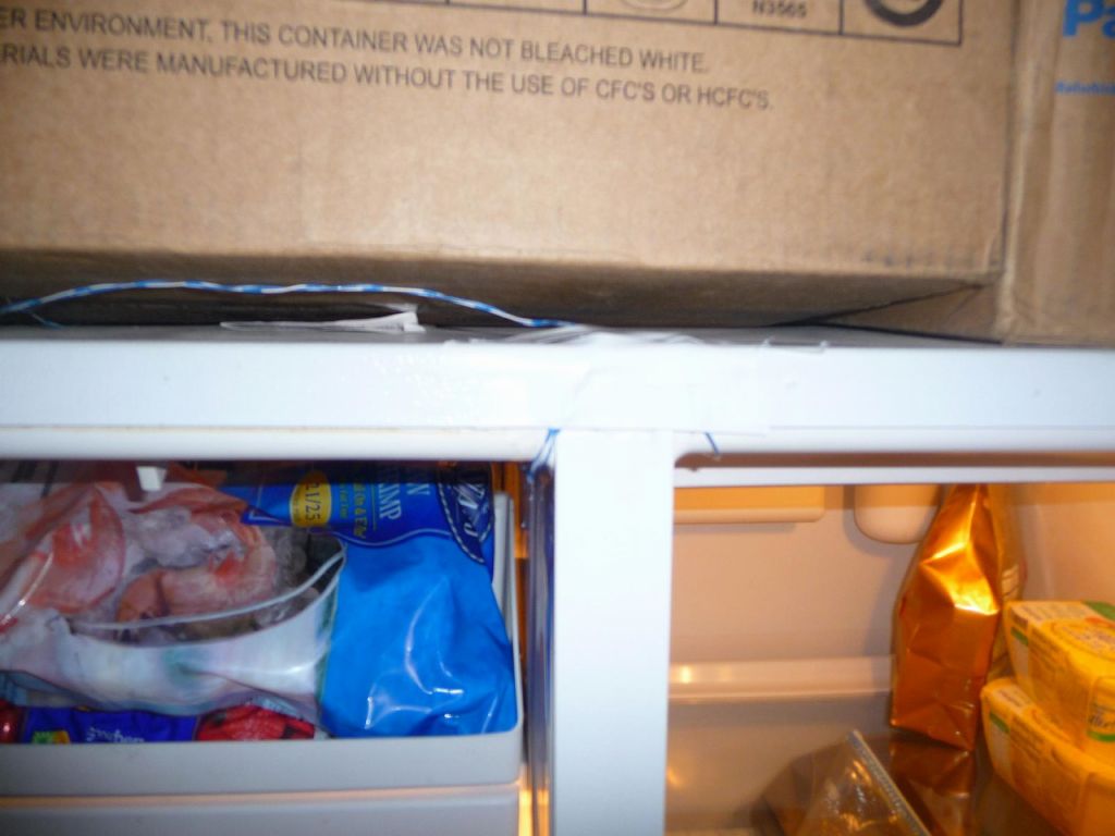
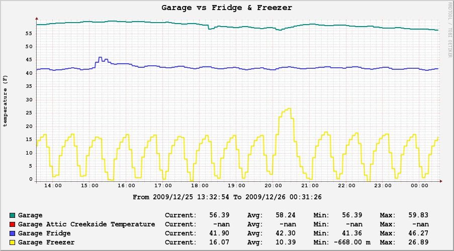
I keep track of my fridge vs freezer temperatures, which is hard to otherwise get on most fridges.
For now I only use the temperature to turn the fan in the computer closet on and off (with a backup that turns it back on every hour just in case misterhouse died), but I am hoping to get more automation of the sort like getting outside air in at the right times of the day to regulate temperature for virtually free when possible (as well as recirculate the air).
You can see the graph above for my computer closet temperature as controlled by an exhaust fan.
Update: I did get around to installing an outside air cooling/heating system, the details are on my Booster Fans and Heating/Cooling with Outside Air with Misterhouse page.
Ideally, instead of using a zone board to turn on the HVAC when the subzone thermostat wants to cool/heat the master bedroom, I would have used misterhouse to tell the secondary thermostat to trigger the HVAC through the first one, but my code wasn't ready then and more importantly I felt that maybe basic functionality in the house should not rely on a computer that I'm the only one who can fix :) (it would also have sucked for the next people if we sell the house and had moved out since the HVAC system would have not worked properly without my computer). |
|